Optical device, method for manufacturing optical device, and projector

a technology for optical devices and manufacturing methods, applied in the direction of projection devices, television systems, instruments, etc., can solve the problems of large number of parts, relatively difficult manufacturing, complicated structure, etc., and achieve the effect of shortening the manufacturing steps, reducing the size of the optical device, and simplifying the structur

Inactive Publication Date: 2005-08-30
SEIKO EPSON CORP
View PDF18 Cites 22 Cited by
  • Summary
  • Abstract
  • Description
  • Claims
  • Application Information

AI Technical Summary

Benefits of technology

[0096]With the optical device according to the fourth aspect of the present invention, the base may be fixed to only one of a pair of end faces intersecting with a light flux incident end face of the color synthesizing optical element, with a linking member for linking the holding members facing one another being provided near the other of the end faces. In the event of such a configuration, integrally forming at least two of the base, the holding member, and the linking member, enables further simplification of the structure and shortening of the manufacturing steps. Thus, this can contribute to further reduction in size of the optical device and an optical apparatus employing this, and further reduction in manufacturing costs. Also, in this case, approximating the thermal expansion coefficients of the integrally formed article and the color synthesizing optical element assembled thereto suppresses warping due to heat. Accordingly, the position of the light modulating device can be held in a suitable state, so that pixel misalignment of the projected image can be avoided, and high-quality images can be obtained.
[0097]With

Problems solved by technology

However, all of the conventional POP structures have a great number of parts and the structure is complicated, because the light modulating devices are fixed by adhesion to the light flux incident end face of the cross-dichroic prism through pins, attaching members, and spacers.
Thus, there is the problem that manufacturing is relatively difficult.
Such problems may consequently obstruct reduction in size of the optical device and lead to increased manufacturing costs.
Further, with pin-spacer type POP structures, adhesive agent remains on the pins and the light flux incide

Method used


Image

  • Optical device, method for manufacturing optical device, and projector
  • Optical device, method for manufacturing optical device, and projector
  • Optical device, method for manufacturing optical device, and projector

Examples


first embodiment

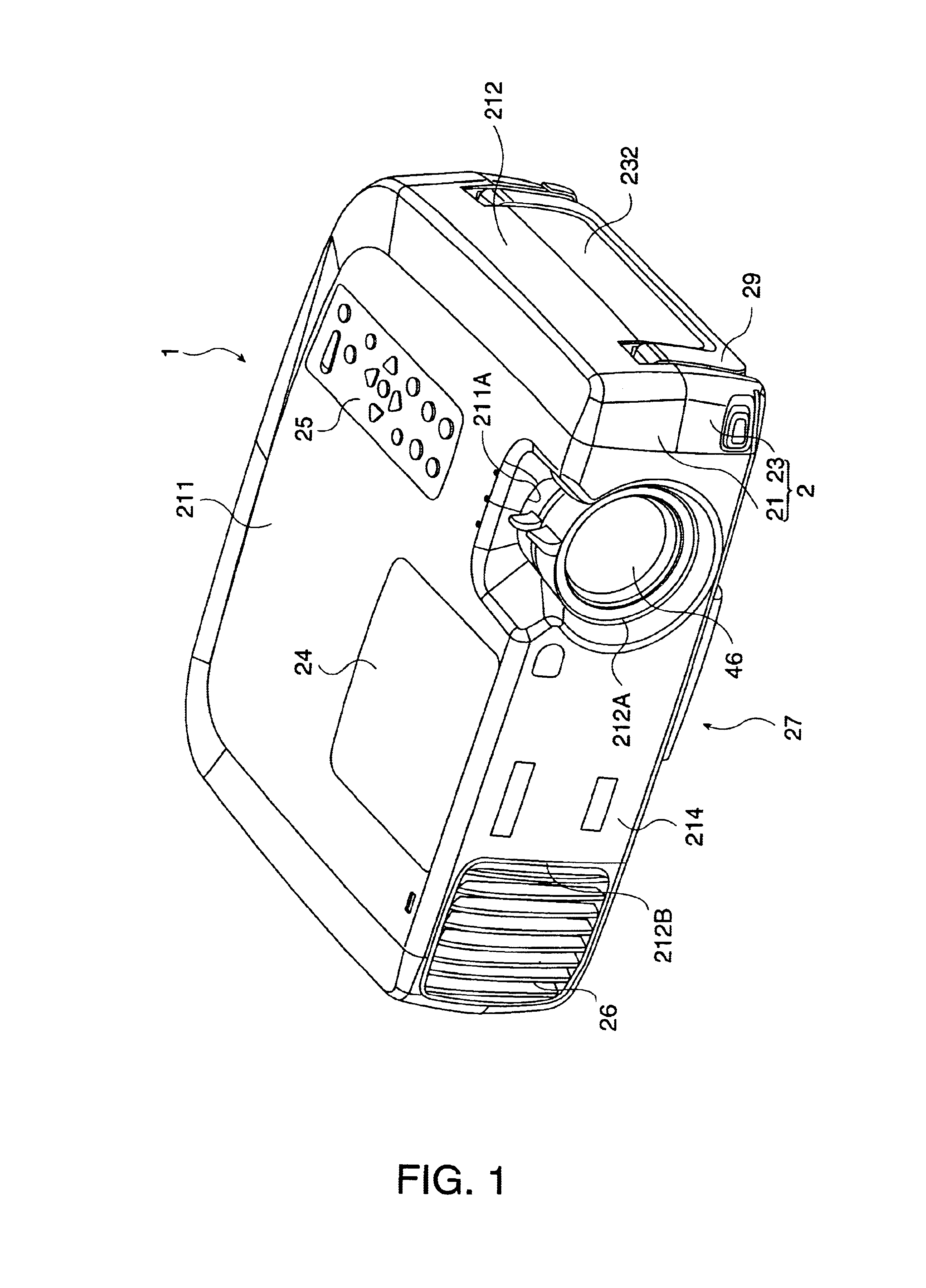
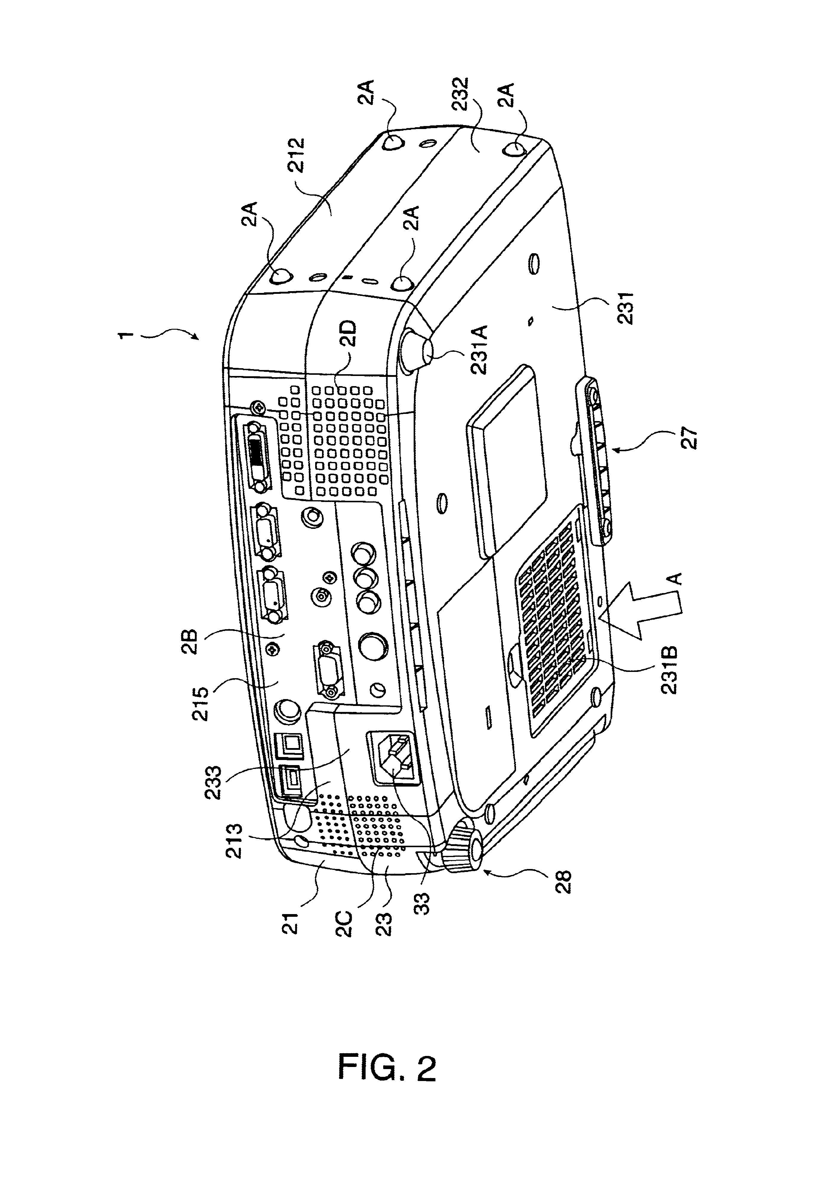
[0154]FIG. 1 is an overall perspective view of an exemplary projector 1 as viewed from above. FIG. 2 is an overall perspective view of the projector 1 as viewed from below. FIG. 3 through FIG. 5 are perspective views of the interior of the projector 1. Specifically, FIG. 3 is a diagram wherein an upper case 21 of the projector 1 has been removed from the state shown in FIG. 1, FIG. 4 is a diagram with a shield plate 80, a driver board 90, and an upper housing 472 removed from the state shown in FIG. 3 as viewed from the rear side, and FIG. 5 is a diagram wherein an optical unit 4 has been removed from the state shown in FIG. 4. The parts 4, 21, 80, 90, and 472, which make up the projector, will be described below in detail.

[0155]In FIG. 1 through FIG. 5, the projector 1 has an external case 2, an electric power source unit 3 stored in the external case 2, and an optical unit 4 disposed in the external case 2 as well, having a U-shaped flat form, with an overall generally rectangula...

third embodiment

[0255]The third embodiment according to the present invention will be described next.

[0256]In the following description, parts and structures the same as with the first embodiment are denoted with the same reference numerals, and detailed description thereof will be omitted or simplified.

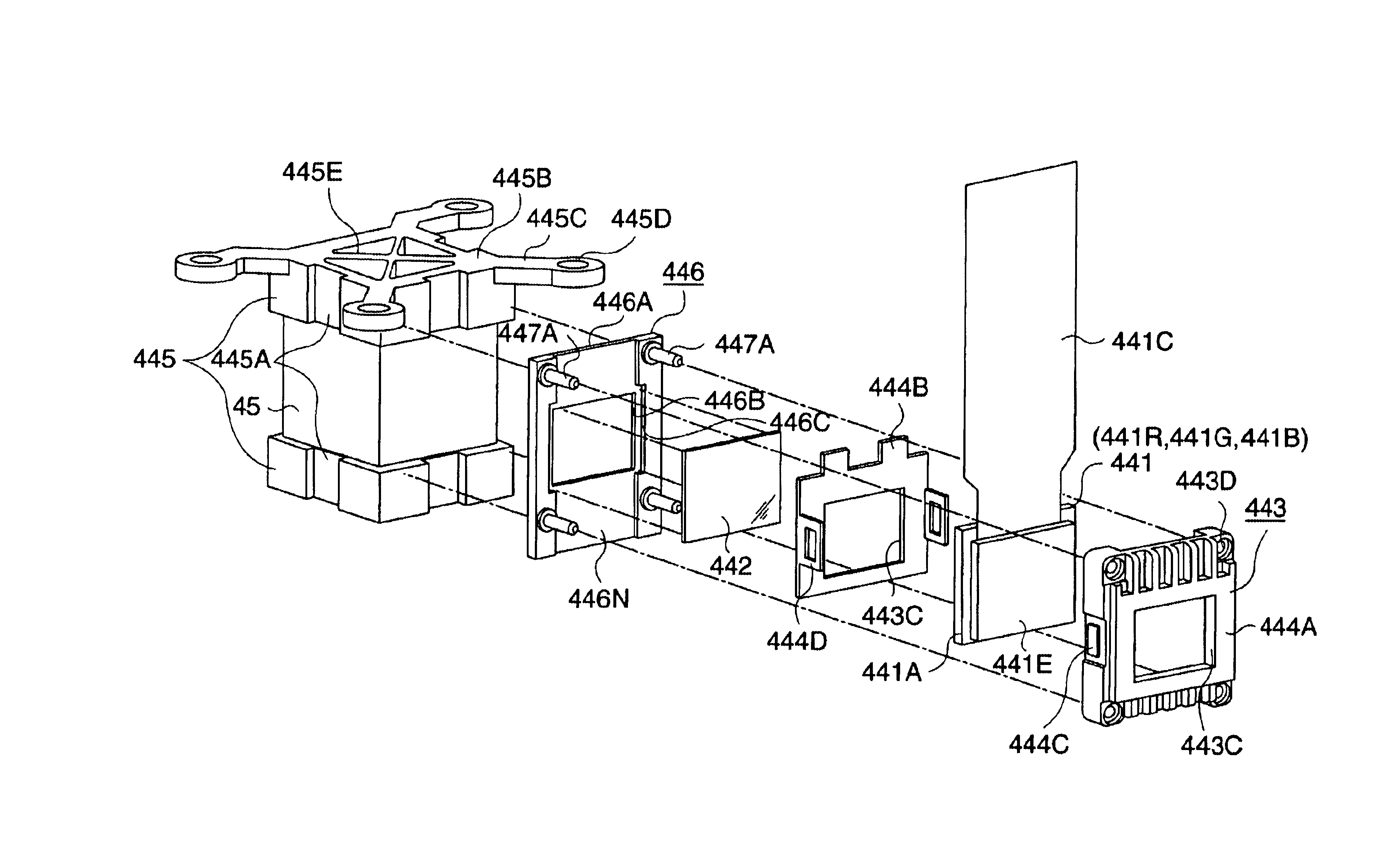
[0257]With the optical device according to the first embodiment, the holding member 446 has pins 447A provided in a protruding condition from the four corners of the rectangular plate-shaped member 446A. Conversely, the optical device according to the third embodiment differs in the point that the holding member 446 has erected pieces 447C with a general L-shape when viewed from the front, as shown in FIG. 16. Other configurations and manufacturing methods are the same as with the first embodiment.

[0258]Specifically, the erected pieces 447C are positioned at the four corners of the rectangular plate-shaped member 446A so as to extend following the edge of the rectangular plate-shaped member 446A, an...

fourth embodiment

[0262]The fourth embodiment according to the present invention will be described next.

[0263]In the following description, parts and structures the same as the first embodiment are denoted with the same reference numerals, and detailed description thereof will be omitted or simplified.

[0264]With the first embodiment, bases 445 are fixed to both the top and bottom faces of the cross-dichroic prism 45 (both of a pair of end faces intersecting the light flux incident end face), with the holding member 446 being fixed by adhesion to the side faces of the bases 445. Further, a polarizing plate 442 is fixed to engaging grooves 446C of the holding member 446 by double-face tape or an adhesive agent.

[0265]Conversely, the fourth embodiment differs in the point that the holding member 446 is fixed by adhesion to the light flux incident end face of the cross-dichroic prism 45, and also, the base 445 is provided on only one of the pair of end faces intersecting with the light flux incident end f...


PUM


Abstract

The present invention provides an optical device that achieves reduction in size, reduction in manufacturing costs, improved image quality, and so forth, by simplification and the like of a panel in prisms (POP) structure wherein light-modulating devices and a color synthesizing optical element are integrally formed. A POP structure is configured wherein pins integrally formed with a holding member are inserted through holes formed in the four corners of holding frames storing the liquid crystal panelsso as to fix the holding frames and holding members by adhesion. End faces of holding members opposite to the pins are fixed by adhesion to the side faces of bases fixed on the upper and lower faces of a cross-dichroic prism.

Description

BACKGROUND OF THE INVENTION[0001]1. Field of Invention[0002]The present invention relates to an optical device wherein a light modulating device for modulating color light according to image information and a color synthesizing optical element for synthesizing color light modulated by the light modulating device are integrally formed, to a manufacturing method for the optical device, and to a projector employing the optical device.[0003]2. Description of Related Art[0004]Conventionally, so-called three-panel projectors are known, which divide a light flux emitted from a light source into color light of the three primary colors of red, green, and blue, by a color separator optical system using dichroic mirrors and the like, and also modulate each color light with three light modulating devices using liquid crystal panels or the like according to image information, synthesize each color light following image modulation with a cross-dichroic prism, and make an enlarged projection of a ...

Claims


Application Information

Patent Timeline
IPC IPC(8): G02F1/01G02F1/00G02F1/1335G02F1/13G03B33/12G02B27/18G02F1/1333G03B33/00G03B21/00G03B21/14H04N9/31H04N5/74
CPCG03B21/00G03B21/14H04N9/3105H04N9/3144G03B21/005G03B21/145A47K13/24E03D9/08H01H37/52H01H83/20
Inventor KITABAYASHI, MASASHIWATANABE, NOBUOFUJIMORI, MOTOYUKIYANAGISAWA, YOSHIYUKIUEHARA, TAISUKEHASHIZUME, TOSHIAKI
Owner SEIKO EPSON CORP
Why Eureka
Try Eureka