Semi-submersible multicolumn floating offshore platform

Active Publication Date: 2005-08-30
HORTON WISON DEEPWATER
View PDF17 Cites 26 Cited by
  • Summary
  • Abstract
  • Description
  • Claims
  • Application Information

AI Technical Summary

Benefits of technology

[0021]A novel method for deploying the MCF platform for offshore operations eliminates the need for a heavy lift vessel or a float-over-deck operation in open seas. The novel deployment method comprises towing the hull (i.e., the base and attached upstanding columns) in a shallow draft configuration from its manufacturing site to an intermediate site in deeper water which is relatively shielded from wind and high waves. At the intermediate site, the hull is ballasted down with sea water to a deep draft configuration such that the tops of the columns extend just above the surface of the water, and a deck barge supporting an associated equipment deck is floated be

Problems solved by technology

Due to their large motions, conventional semi-submersible platforms cannot support high-pressure, top-tensioned risers.
The compartmentalization of the columns with bulkheads substantially increases the manufacturing costs of the platform, especially when a high degree of compartmentalization is effected.
Additionally, the methods by which the platforms are deployed for offshore operations are not optimal.
In either case, the procedure is typically effected far offshore (e.g., 100 miles, or 161 km), is performed in open seas, and is strongly dependant on weather conditions

Method used


Image

  • Semi-submersible multicolumn floating offshore platform
  • Semi-submersible multicolumn floating offshore platform
  • Semi-submersible multicolumn floating offshore platform

Examples


Embodiment Construction

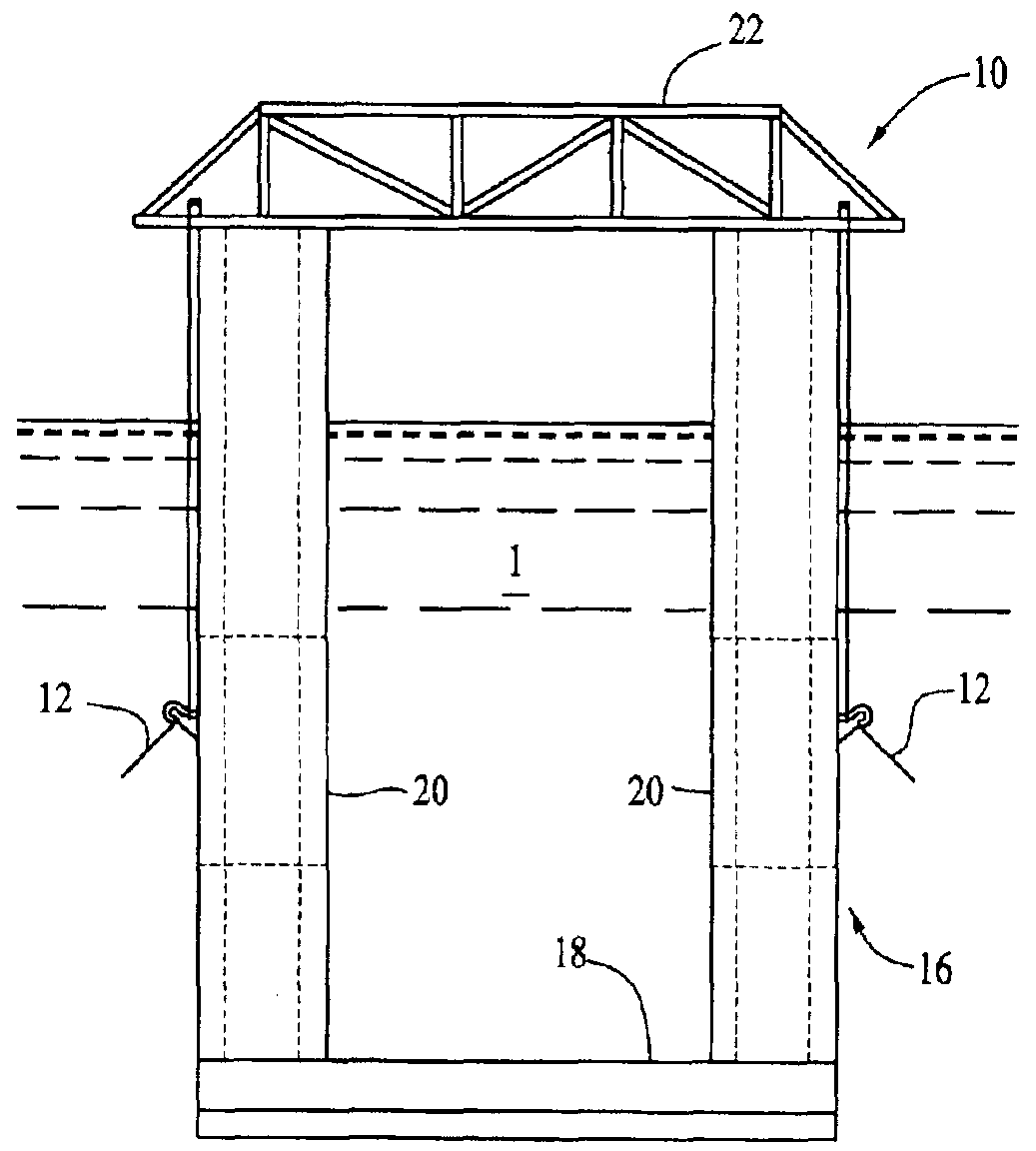
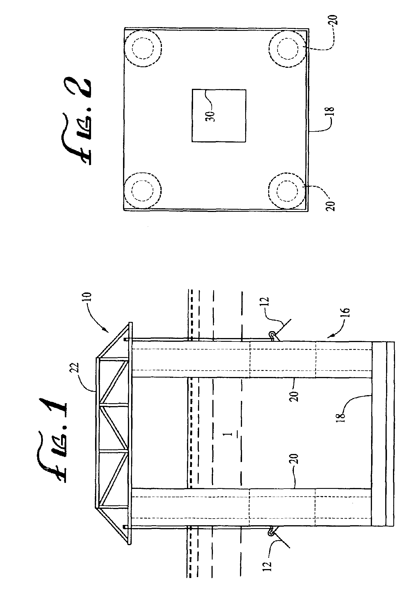
[0041]FIG. 1 is an elevation view of an exemplary embodiment of a semi-submersible multicolumn floating offshore platform 10, or “Multi-Column Floater” (“MCF”), in accordance with the present invention, shown deployed in a body of water 1 in a deep draft operational configuration and anchored over an operation site with a taut leg mooring system 12. The MCF is shown deployed in a similar configuration in the elevation view of FIG. 12, anchored at an operation site by a conventional catenary mooring system 14.

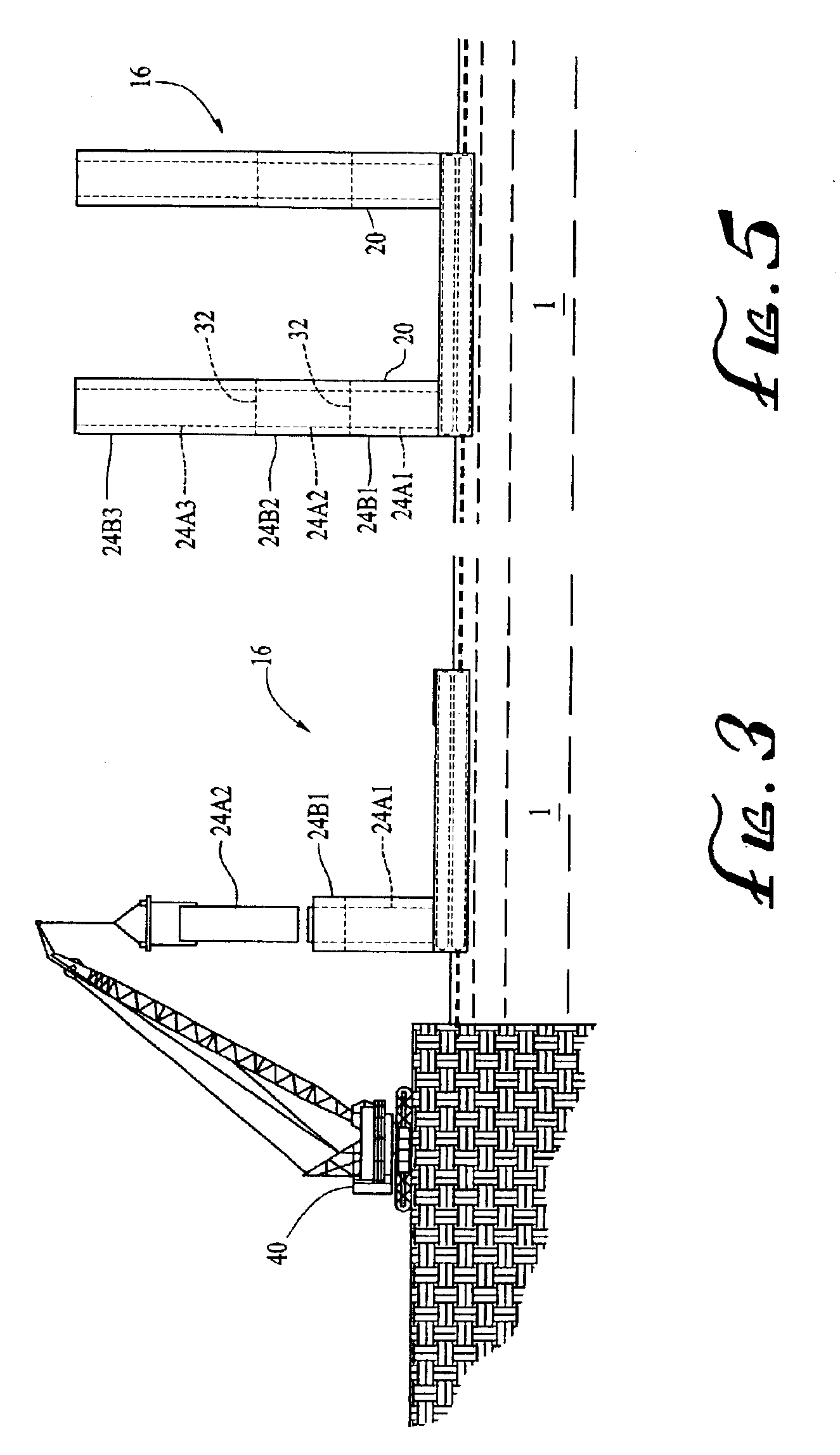
[0042]As shown in the figures, the exemplary MCF 10 comprises a floating hull 16 having an adjustably buoyant base 18, a plurality of adjustably buoyant columns 20 vertically upstanding from the base 18, and a work platform, or equipment deck 22, that is supported atop the columns 20 when the platform is operationally deployed. Each of the columns 20 of the hull 16 comprises a cellular structure that includes a plurality of elongated tubes 24 (see FIGS. 13-16) extending from the...


PUM


Abstract

A semi-submersible, multicolumn, deep draft, floating offshore oil and gas drilling and production platform comprises a floating hull having an adjustably buoyant base, a plurality of columns vertically upstanding from the base, and an equipment deck that is supported atop the columns when the platform is operationally deployed. Each of the columns comprises a cellular structure that includes a plurality of elongated tubes having a variety of cross-sectional shapes extending from the base to the top of the column. Each of the tubes defines one or more closed compartments. At least one of the compartments has a buoyancy that is fixed, and at least another one of the compartments has a buoyancy that is adjustable. The buoyancy of the compartments and the base can be controllably adjusted with pressurized air to provide a safer and less costly method for deploying the platform for offshore operations.

Description

CROSS-REFERENCE TO RELATED APPLICATIONS[0001](Not Applicable)STATEMENT REGARDING FEDERALLY SPONSORED RESEARCH OR DEVELOPMENT[0002](Not Applicable)REFERENCE TO APPENDIX[0003](Not Applicable)BACKGROUND OF THE INVENTION[0004]1. Field of the Invention[0005]The present invention relates to floating offshore platforms in general, and in particular, to an adjustably buoyant, deep draft, semi-submersible platform for off-shore oil and gas drilling and production operations.[0006]2. Description of Related Art[0007]Conventional shallow draft semi-submersible offshore platforms are used primarily in offshore locations where water depth exceeds about 300 feet (91 meters). This type of semi-submersible platform comprises a hull structure that has sufficient buoyancy to support a work platform above the water surface, as well as rigid and / or flexible piping extending from the work platform to the seafloor, where one or more drilling or well sites are located.[0008]The hull typically comprises a p...

Claims


Application Information

Patent Timeline
IPC IPC(8): B63B9/00B63B43/00B63B1/10B63B1/00B63B9/06B63B43/12B63B35/44B63B11/00B63B11/02B63G8/00B63G8/22
CPCB63B1/107B63B9/065B63B11/02B63B35/4413B63B43/12B63B2009/067B63G8/22B63B39/03B63B77/00B63B75/00
Inventor HORTON, III, EDWARD E.
Owner HORTON WISON DEEPWATER
Why Eureka
Try Eureka