Low cycle fatigue life (LCF) impeller design concept

a technology of impellers and design concepts, applied in the direction of liquid fuel engines, vessel construction, marine propulsion, etc., can solve the problems of low cycle fatigue life, low lcf life, and again commercially unviable lcf, and achieve the effect of improving the low cycle fatigue li

Inactive Publication Date: 2005-08-30
PRATT & WHITNEY CANADA CORP
View PDF15 Cites 25 Cited by
  • Summary
  • Abstract
  • Description
  • Claims
  • Application Information

AI Technical Summary

Benefits of technology

[0011]In accordance with a still further general aspect of the present invention, there is provided a device for improving the low cycle fatigue (LCF) life of a gas turbine engine impeller having axially spaced-apart front and rear end portions, t

Problems solved by technology

Unfortunately, this high compressor delivery temperature creates high temperature regions on the rear cavity of the impeller.
Titanium, at these high temperatures, suffers from creep/fatigue interaction as well as oxidat

Method used


Image

  • Low cycle fatigue life (LCF) impeller design concept
  • Low cycle fatigue life (LCF) impeller design concept
  • Low cycle fatigue life (LCF) impeller design concept

Examples


Embodiment Construction

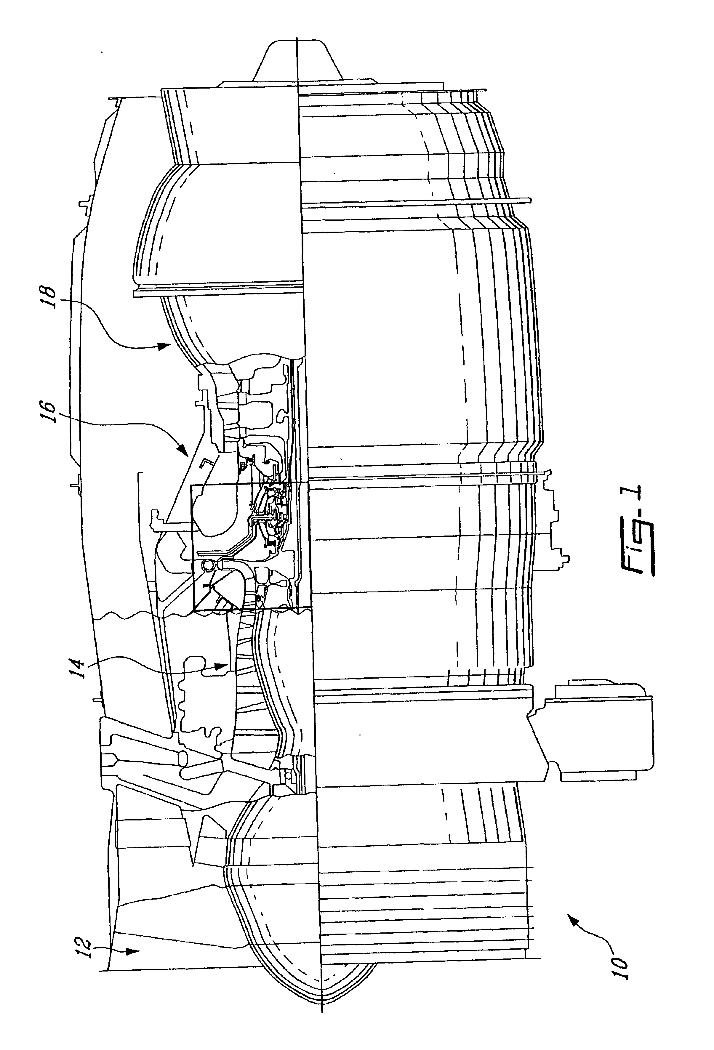
[0015]FIG. 1 illustrates a gas turbine engine 10 generally comprising in serial flow communication a fan 12 through which ambient air is propelled, a multistage compressor 14 for pressurizing the air, a combustor 16 in which the compressed air is mixed with fuel and ignited for generating hot combustion gases, and a turbine 18 for extracting energy from the combustion gases.

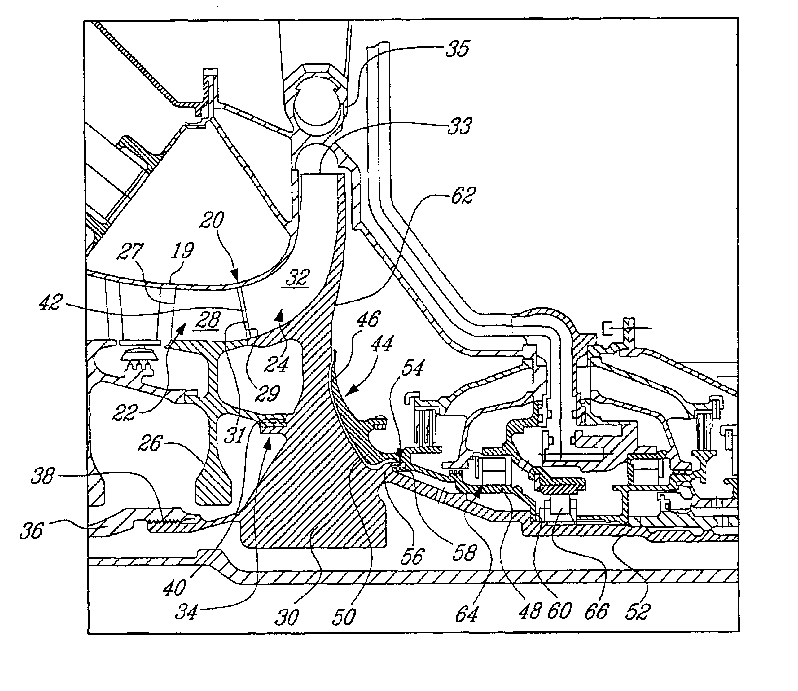
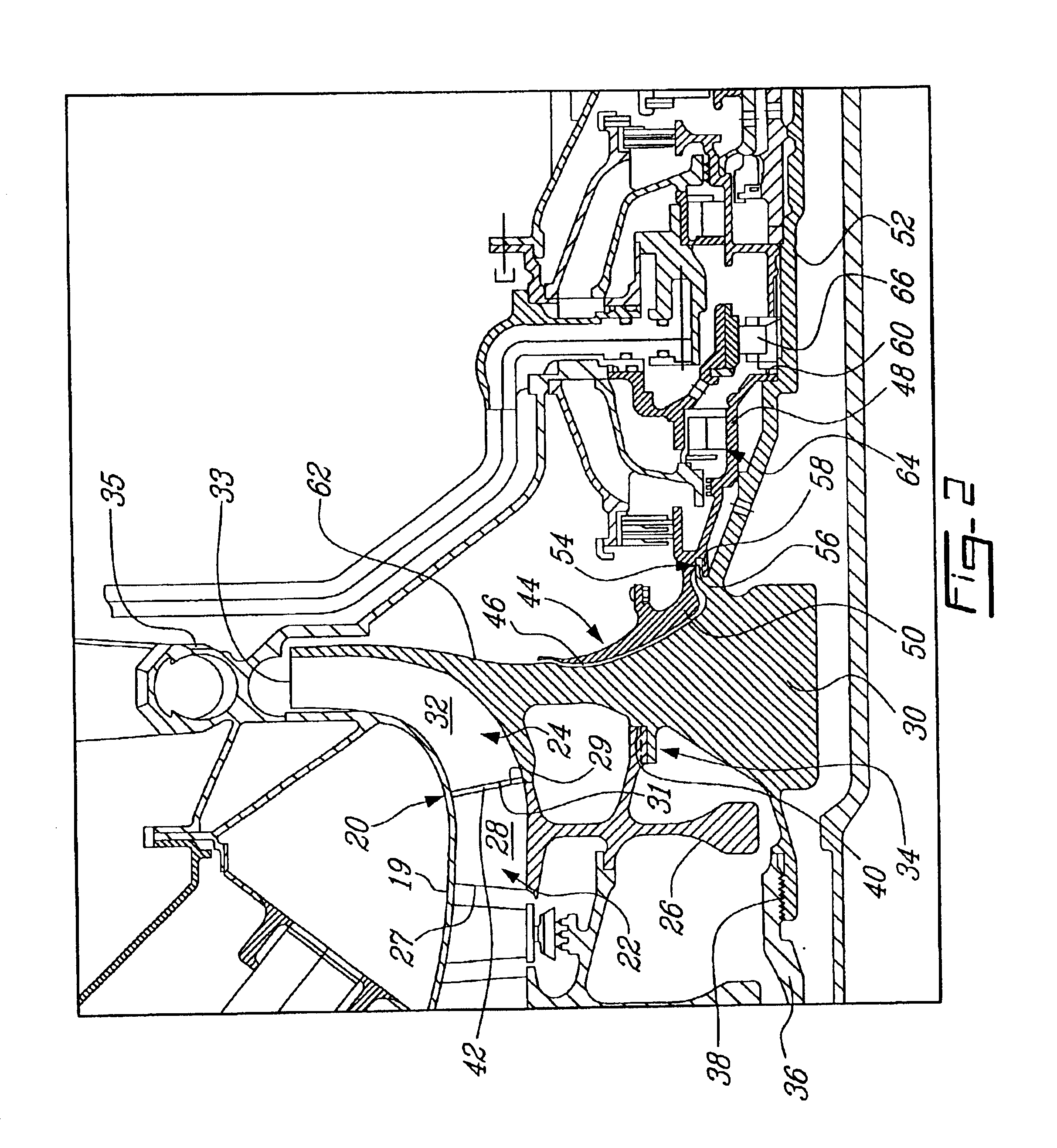
[0016]As shown in FIG. 2, the multistage compressor 14 includes among others a shroud 19 surrounding a two-piece impeller 20 including an inducer 22 and a separate exducer 24. The inducer 22 includes a hub structure 26 and a set of circumferentially spaced-apart blades 28 (only one of which is visible in FIG. 2) extending radially outwardly from the hub structure 26. Each blade 28 extends from a leading edge 27 to a trailing edge 29. The inducer blades 28 have mostly axial flow characteristics. The exducer 24 includes a hub structure 30 and a set of circumferentially spaced-apart curved blades (only one of which ...


PUM


Abstract

A rotor assembly for a gas turbine engine, having a rotor member with axially spaced-apart front and rear end portions. A thermal shield is located axially downstream of the rear end portion of the rotor for thermally shielding the same from the hot surrounding environment. The thermal shield includes a rear coverplate and an axial gap between the rear coverplate and the rear end portion of the rotor member.

Description

BACKGROUND OF THE INVENTION[0001]1. Field of the Invention[0002]The present invention generally relates to gas turbine engines and, more particularly, to rotor members for such gas turbine engines.[0003]2. Description of the Prior Art[0004]At present, most of the world's small aircraft gas turbine engines incorporate a multi-stage titanium compressor. Typically, the first stages are axial compressors and the last stage is a one-piece centrifugal impeller. Typical compressor delivery temperatures are around 850° F. (at the tip of the impeller) and the bore air temperature is around 600° F. The resulting delta T between the two locations is roughly 250° F. With this delta T, the industry has been able to achieve adequate low cycle fatigue (LCF) lives.[0005]Recent demands to improve the engine fuel consumption have resulted in the compressor delivery temperature increasing to 1000° F. and greater. Unfortunately, this high compressor delivery temperature creates high temperature regions...

Claims


Application Information

Patent Timeline
IPC IPC(8): F01D25/14F01D25/08F01D5/02F01D5/04
CPCF01D5/046F01D5/048F01D25/14Y02T50/673Y02T50/675Y02T50/60
Inventor ROMANI, GIUSEPPESTONE, PAUL
Owner PRATT & WHITNEY CANADA CORP
Why Eureka
Try Eureka