Atraumatic insertion of a subcutaneous device

Inactive Publication Date: 2005-08-30
NOVO NORDISK AS
18 Cites 1014 Cited by

AI-Extracted Technical Summary

Problems solved by technology

Although the latter indeed is of great importance, it is basically a materials problem which will not be addressed further in this applica...

Benefits of technology

[0016]Having regard to the above discussion of the prior art, an object of the present invention is to provide an improved concept for the transcutaneous placement of a sensor device, the concept reducing the severity of the body response thereby allowing for more accurate measurements and/or a reduced need for recalibration of the sensor during ...

Abstract

The invention relates to a concept for placing a subcutaneous device such as a sensor at a selected site within the body of a patient, e.g. to obtain blood glucose readings. In a first aspect, an insertion needle comprises an oblong needle body and a distal end portion, the distal end portion having a pointed distal tip allowing the needle to be introduced subcutaneously and a distally facing generally smooth surface, the body comprising along a portion thereof a longitudinal groove adapted to at least partially accommodate the subcutaneous device. In a second aspect, a combination of an insertion needle and a subcutaneous device form an oblong body portion and a distal end portion formed by either of the members or in combination by the two members, the distal end portion having a pointed distal tip and a distally facing generally smooth surface. By the above configuration, a concept is provided reducing the severity of the body response following transcutaneous placement of a device as well as reducing the pain associated with the insertion.

Application Domain

Technology Topic

Smooth surfaceDevice form +1

Image

  • Atraumatic insertion of a subcutaneous device
  • Atraumatic insertion of a subcutaneous device
  • Atraumatic insertion of a subcutaneous device

Examples

  • Experimental program(1)

Example

[0059]It should be noticed that the figures are for illustrating the principles of the invention only and are not necessarily drawn to scale.
DESCRIPTION OF THE PREFERRED EMBODIMENTS
[0060]It should be emphasized that in the following disclosure of the invention, features and details which are not considered necessary for understanding the principles of the present invention has been largely omitted, for example, the sensor device is shown merely schematically, the attachment to a mounting base or similar structure or the provision of sensor electrodes and electric contact means being omitted.
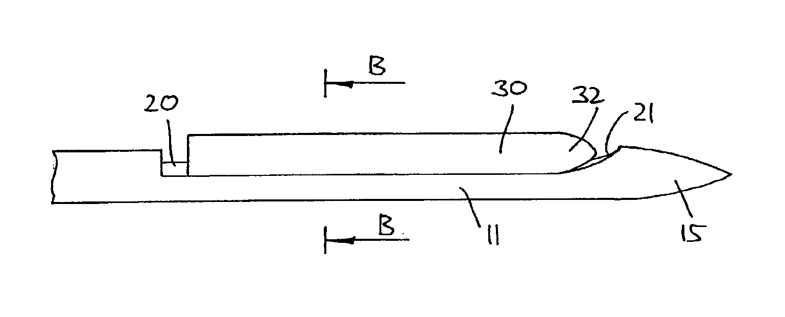
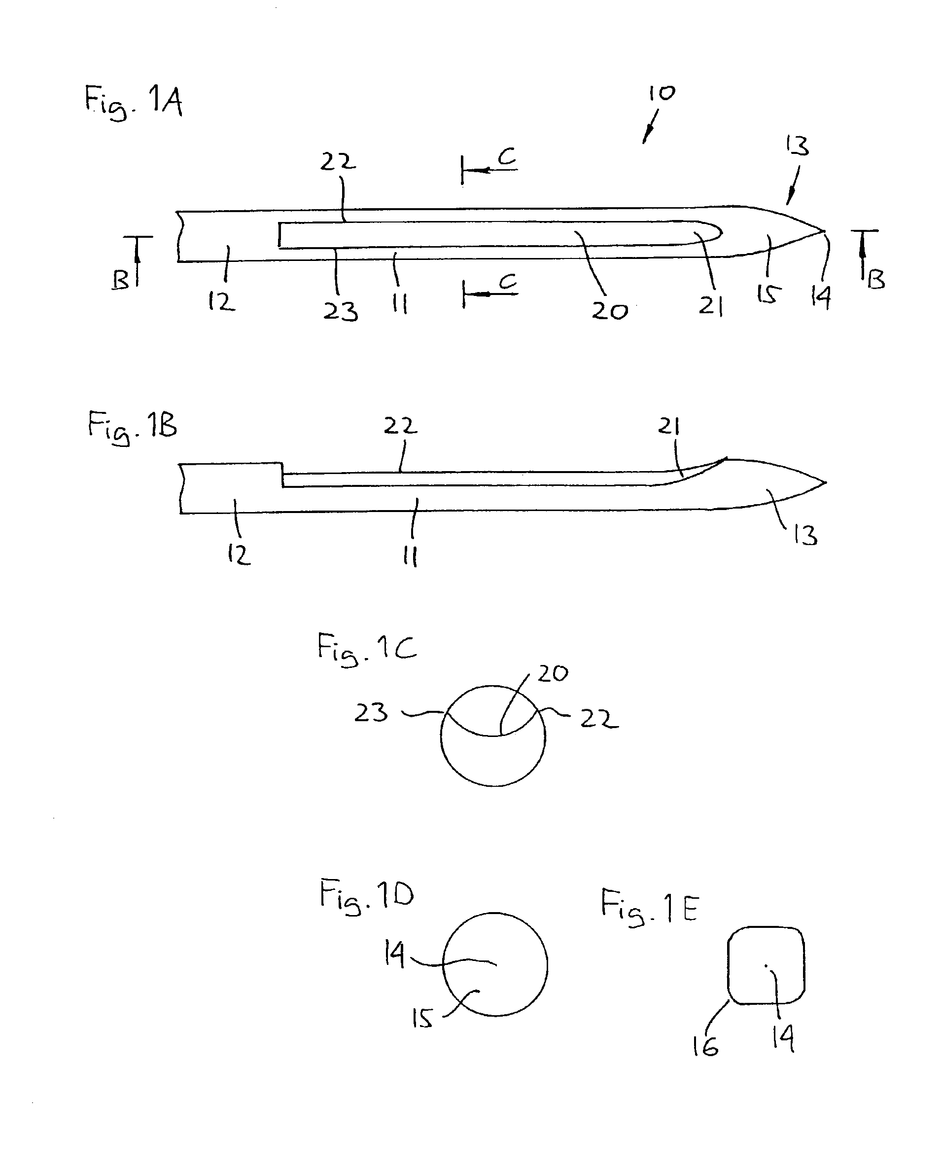
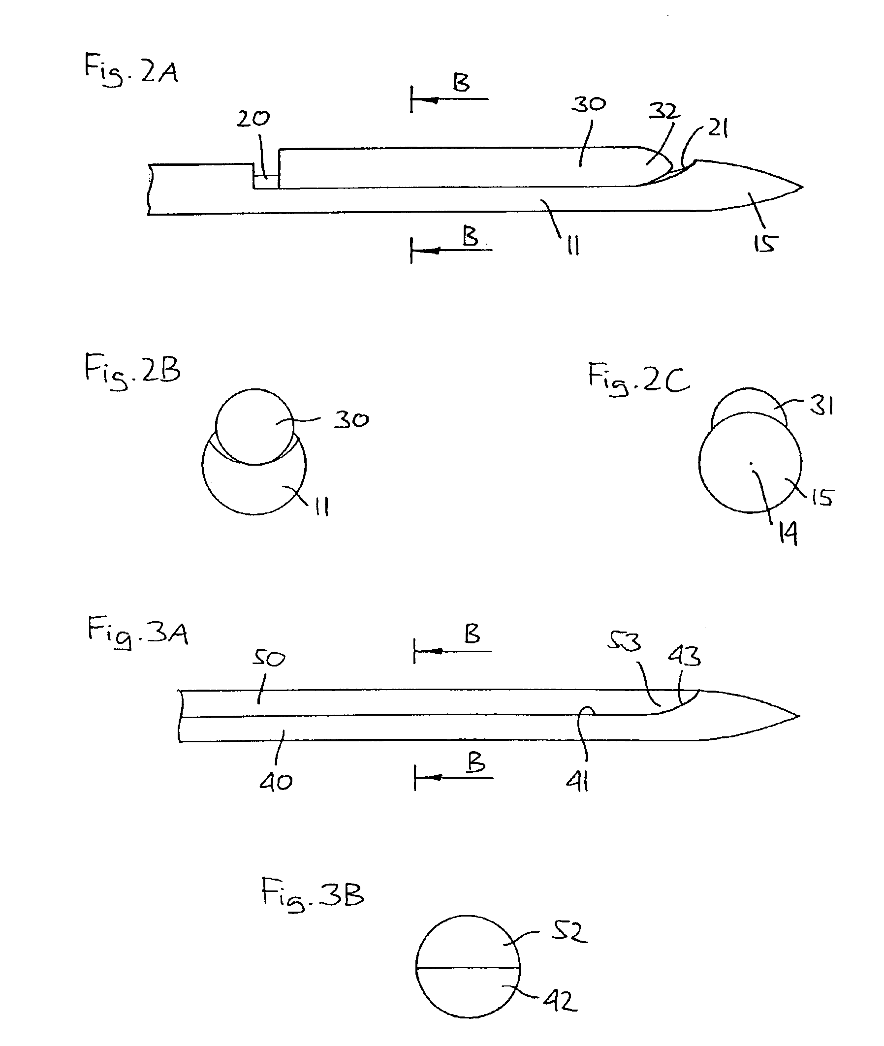
[0061]FIGS. 1A-1E shows an embodiment of the invention in accordance with a first aspect. More specifically an insertion needle 10 comprises an oblong needle body 11 having a proximal portion 12 and a distal end portion 13, the distal end portion having a generally conical shape providing a pointed distal tip 14 and a distally facing smooth surface 15, thereby comprising no structures which may serve to cut tissue when the insertion needle is introduced subcutaneously. As appears from FIG. 1D the conical end portion completely defines the distal surface, the needle body comprising no protruding portions or element.
[0062]The needle body defines a general axis for the insertion needle, a longitudinal groove 20 being formed in the needle body coaxially therewith. As appears from FIG. 1A, the groove terminates in the vicinity of the distal end portion (i.e. just proximally of the conical portion), the groove having a ramp 21 formed distally (see FIG. 1B), the ramp facing outwardly-proximally relative to the needle body. Between the groove and the outer surface of the needle body two opposed edges 22, 23 are formed which preferably are rounded (not shown in FIG. 1C) to avoid any cutting action when the insertion needle is moved relative to the tissue.
[0063]The groove is adapted to at least partially accommodate a sensor device of which a distal end may slide on the ramp thereby forcing the sensor device outwardly relative to the insertion needle as will be described in greater detail below.
[0064]In the shown embodiment the groove terminates short of the distal and proximal end portions, however, it may extend along the full length of the needle body just at it may extend into the distal end portions, indeed, in which case the edge formed between the groove and the conical surface should be properly rounded to avoid any cutting action.
[0065]The shown insertion device has a general circular cross-section (not considering the groove) with a symmetrical “purely” conical end portion, however, the conical portion may be asymmetric, i.e. the pointed tip may be shifted towards a side, just as the cross-section may be non-circular, e.g. square with rounded edges 16 as illustrated in FIG. 1E. Indeed, the insertion needle may have varying cross-sections along the length thereof.
[0066]The insertion needle shown in FIGS. 1A-1C may be used with a sensor device which is partly or fully accommodated in the groove, i.e. the sensor device may be protruding or non-protruding in a cross-sectional view. In case the sensor device is fully accommodated in the groove, it may fully or partly “fill” the groove. An advantage with this arrangement is that the distal end of the sensor device is well protected against external forces during insertion, especially axial forces acting on the distally facing surface, which forces may act to displace or deform the sensor device. However, if deemed necessary, additional gripping means securing the sensor device during insertion may be provided as will be described in greater detail below.
[0067]As shown in FIGS. 2A-2C, a combination of an insertion needle 10 as described above and a sensor device 30 is provided, the sensor device being arranged in the groove 20 and is partly accommodated therein. As appears from FIGS. 2A-2C the sensor protrudes from the “virtual” circumference of the cylindrical needle body and thus beyond the conical distal surface of the insertion body as seen in FIG. 2C. However, in order to provide a smooth “combined” distal surface, i.e. made up of the distal surface of the introduction needle and the distally facing surface 31 of the protruding portion of the sensor device as seen in FIG. 2C, the latter is formed with a rounded distal end 32. As described above, axial forces acting on a protruding distally facing surface 31 may act to displace or deform the sensor device. Correspondingly, the sensor device and the insertion needle may be provided with releasable cooperating gripping means securing the sensor device during insertion, yet allowing easy withdrawal of the insertion needle.
[0068]With reference to FIGS. 1 and 2, an insertion needle being provided with a recess in the form of a groove was described, however, the recessed area may have any desirable configuration serving the object of “nesting” the subcutaneous device to be inserted. FIGS. 3A and 3B show a combination of an insertion needle 40 and a sensor device 50, the needle comprising a recessed portion 41 accommodating the sensor, each component having a semicircular cross-sectional configuration 42, 52 thereby combining to form a circular body portion. As for the above-described embodiment, the recess terminates in a ramp 43, however, in contrast to above, the distal end 53 of the sensor is adapted to fully engage the ramp surface.
[0069]Next reference is made to FIGS. 4-8 disclosing combinations of an insertion needle (in the following also termed needle) and a sensor device, the combined device having a distal end portion with a pointed distal tip and a distally facing generally smooth surface comprising no cutting edges.
[0070]FIG. 4A shows the distal portions of a slotted insertion needle 60 and a therein-mounted sensor device 70, the slot extending from the distal end and fully or partly to a proximal end, thereby forming a longitudinally extending groove 61. The slotted (part of the) needle has a part-circular cross sectional shape with an arcuate dimension or span greater than 180 degrees, e.g. a span of about 210 degrees which leaves a longitudinal slot in the needle with an arcuate dimension of about 150 degrees, which cooperates with the part-circular shape of the sensor device to define a substantially full-circle geometry for facilitated insertion through the patient's skin, see FIG. 4B. More specifically, the sensor device comprises a core 71 and two lateral flanges 72, 73, the core being gripped by the insertion needle and are thereby slidingly accommodated therein. The needle and sensor device are thus mechanically interlocked to prevent lateral dislocation of the latter from the insertion needle, while permitting longitudinal sliding motion of the needle over the sensor device.
[0071]The distal or free ends of the needle and the sensor device are set at an oblique angle to thereby form a common, smooth distal surface 74 providing a pointed distal end 64, the edges between the distal surface and the general circumference being properly rounded to prevent any cutting action when introduced subcutaneously, the rounded portion providing a needle distal surface 65. The shown rounding of the edges in the vicinity of the pointed end ensures that the pointed end is formed by the needle, the needle preferably being made form medical grade stainless steel, which allows the sensor to be formed from a relatively soft polymer less suitable for forming the pointed end.
[0072]In the shown embodiment the needle edge is rounded with a radius of curvature corresponding approximately to the wall thickness of the needle, which may be 0.2 mm for a needle having an outer diameter of 0.7 mm, however, a non-cutting radius of curvature may be less than 0.1 mm or even less than 0.02 mm.
[0073]As appears, the sensor devices depicted in the different figures are shown “in solid” as they merely serve to illustrate the outer physical configuration thereof. With reference to FIG. 4D an example of a sensor arrangement mounted in an insertion needle 260 is shown, the sensor device being in the form of a cannula 270 comprising first and second lumen portions 271, 272, the first providing structural strength and having a part circular cross section to be fitted within the insertion needle, the second being adapted for receiving, protecting and guidably supporting a portion of the sensor element 275 per se. A window 276 is formed in the second lumen near the distal end thereof, in general alignment with the sensor electrodes 277 of the sensor element, to permit direct electrode exposure to patient body fluid when the sensor is transcutaneously placed. The cannula may be constructed from any suitable medical grade plastic or elastomer, such as polytetrafluoroethylene or silicone.
[0074]FIG. 5A shows the distal portions of a slotted insertion needle 80 and a therein-mounted sensor device 90. The slotted needle has a part-circular cross sectional shape with an arcuate dimension greater than 180 degrees which cooperates with the part-circular shape of the sensor device to provide a grip between the two members, see FIG. 5C, this essentially corresponding to the configuration of the above-described embodiment (FIG. 4B). However, in contrast to the previous embodiment, the needle is mainly solid, the solid portion 81 having a semicircular configuration with flange members 82 providing the gripping means. The two members form in combination a distal end portion having a pointed distal tip 83 and a distally facing smooth conical surface formed in combination by the distal surfaces 84, 94 of the two members. As was also the case above, the pointed end is provided by the needle, which necessitates the “solid” configuration of the needle. Indeed, in case the pointed tip is shifted away from the groove, a needle with a less solid cross-sectional configuration could be used. In case the tip was shifted entirely downwardly (in the figures), an overall configuration resembling the embodiment of FIG. 4A would result.
[0075]With reference to FIGS. 1-5, embodiments in which the pointed distal tip have been provided by a needle are described, however, by using a suitable (polymer) material for the sensor device, the pointed distal tip may be formed integrally therewith, this allowing for a simpler configuration of the needle (which then correctly may be denoted merely an insertion device)—or the insertion device may be entirely dispensed with.
[0076]Correspondingly, FIG. 6A shows the distal ends of a slotted insertion device 100 and a therein-mounted sensor device 110, the slot extending from the distal end and fully or partly to a proximal end, thereby forming a longitudinally extending groove 101. The slotted (part of the) insertion device has a part-circular cross sectional shape with an arcuate dimension or span greater than 180 degrees, e.g. a span of about 210 degrees which leaves a longitudinal slot in the insertion device with an arcuate dimension of about 150 degrees, which cooperates with the part-circular shape of the sensor device to define a substantially full-circle geometry for facilitated insertion through the patient's skin, see FIG. 6B. More specifically, the sensor device comprises a core 111 and two lateral flanges 118, 119, the core being gripped by the insertion device and slidingly accommodated therein. The insertion device and sensor device are thus mechanically interlocked to prevent lateral dislocation of the latter from the insertion device, while permitting longitudinal sliding motion of the needle over the sensor device.
[0077]The distal end portion 112 having a pointed distal tip 113 and a distally facing smooth conical surface is formed entirely by the distal surface 114 of the sensor device 110, the insertion device solely serving as a support member providing a desired amount of stiffness.
[0078]In an even simpler embodiment of the present invention, the introduction device is fully dispensed with. More specifically, FIG. 7 shows a distal portion of a sensor comprising a distal body portion 121 and a distal end portion 122 having a pointed distal tip 123 and a distally facing smooth conical surface 124 formed entirely by the sensor device. The schematically shown sensor element 125 may represent a sensor element per se or a window covering such an element, this as described above.
[0079]Indeed, for a sensor device adapted to be introduced without a supporting insertion needle, a suitable balance between a desirable high rigidity during insertion and a high degree of flexibility when carried subcutaneously by a patient should be found, however, by using appropriate additional insertion means, it would be possible to insert even a relatively flexible sensor device. More specifically, insertion devices are known into which subcutaneous devices can be mounted, the insertion device comprising a user-releasable means for “driving” the device subcutaneously, e.g. by releasing a spring, this allowing a pointed but relatively flexible sensor device to be introduced.
[0080]The sensor device shown in FIG. 7 may also comprise an internal channel allowing a rigid support to be mounted therein during insertion.
[0081]In the above, insertion needles and sensor devices have described which are adapted to be arranged in a side-by-side configuration. In contrast, FIG. 8A shows the distal ends of a solid insertion needle 130 mounted through a sensor device 140 formed as a cannula. The two members form in combination a distal end portion having a pointed distal tip 131 and a distally facing smooth conical surface formed in combination by the distal surfaces 132, 142 of the two members. FIG. 8B shows an example of a prior art cannula 135 in combination with an “atraumatic” insertion needle 145. As appears, the two members do not form a common rounded surface and thus fail to provide for substantially atraumatic insertion.
[0082]Next, with reference to FIG. 9, a transcutaneous sensor insertion set 300 designed to place a sensor subcutaneously or at another selected site within the body of a patient, in a manner minimizing patient discomfort and trauma will be described. The flexible electrochemical sensor device 310 having a distal (or subcutaneous) portion 311 and a proximal portion 312 may be constructed according to so-called thin film mask techniques to include elongated thin film conductors embedded or encased between layers of a selected insulating material. The sensor electrodes 315 at the distal end portion are exposed through one of the insulating layers for direct contact with a patient body fluid (e.g. blood), when the distal portion of the sensor device is transcutaneously placed. By the term “flexible” in this context is meant that the sensor device along the length thereof is more flexible than the insertion needle.
[0083]The sensor 310 is carried by a mounting base 320 adapted for placement onto the skin of a patient. The mounting base comprises a generally rectangular pad having an upper surface 322 and an underside surface coated with a suitable pressure sensitive adhesive layer 321, with a peel-off paper strip (not shown) normally provided to cover and protect the adhesive layer, until the insertion set 300 is ready for use. The base further comprises an opening 325 through which the sensor device is arranged, the distal portion 311 protruding from the underside surface, the proximal portion 312 being carried by the upper surface. The proximal portion terminates in suitable conductive contact means 316 adapted for electrical connection to suitable signal processing means (not shown) for monitoring patient condition in response to signals derived from the sensor electrodes.
[0084]The insertion needle 330 is adapted for reception through a needle port 331 formed in the upper base and further through the opening 325. As appears, the insertion needle is of the same general configuration as shown in FIG. 1A, having a conically formed distal end portion 132 with a pointed tip 333 and an open groove 334 which extends longitudinally from just proximally of the tip at the underside of the needle to a position at least within the opening, the groove comprising a ramp formed distal portion 336. For the shown needle configuration, the opening 325 and the port 331 are “oversized” compared to the cross-section of the combined insertion needle and sensor distal portion, this allowing the wider distal portion of the insertion needle to be withdrawn. However, for other embodiments (e.g. corresponding to FIGS. 3-8) the needle may be received in slide-fit engagement through the opening and the port. Above the mounting base 320, the insertion needle may have a full round cross sectional shape, the rear end being anchored to an enlarged hub 335 adapted for easy grasping and handling between the thumb and index finger. Preferably the hub comprises guiding or locking means (not shown) for matingly engaging corresponding alignment or locking means on the mounting base.
[0085]In use, the insertion set 300 allows for quick and easy transcutaneous placement of the sensor distal portion 111 at a selected site within the body of a patient. More specifically, the peel-off strip is removed from the mounting base, at which time the mounting base 320 can be pressed onto and seated upon the patient's skin. During this step, the insertion needle 130 pierces the patient's skin and carries the needle-formed distal portion to the appropriate transcutaneous placement site. During insertion, the needle provides a stable support and guide structure to carry the flexible sensor device to the desired insertion site.
[0086]When the sensor device is transcutaneously placed, with the mounting base seated upon the patient's skin, the insertion needle 330 can be slidably withdrawn from the patient. During this withdrawal step, the insertion needle slides over the sensor device (to be described below) leaving the distal portion of the sensor with electrodes 115 thereon at the selected insertion site. These electrodes are directly exposed to patient body fluid (for example via a window as shown in FIG. 4D). The sensor proximal portion is appropriately coupled to processing means (not shown), so that the sensor can then be used over a given period of time for taking blood chemistry readings, such as blood glucose readings in a diabetic patient. If desired, the distal portion may comprise a lumen (as shown in FIG. 4D) available to deliver medication and/or sensor calibration fluid to the vicinity of the electrodes, or alternately to withdraw patient fluid such as blood for analysis.
[0087]In case the configuration of the insertion needle and the sensor device correspond to the embodiments shown in FIGS. 3-8 the needle can be withdrawn from the sensor device without moving the latter, however, for the embodiments shown in FIGS. 1, 2 and 9, the sensor device 150 will be forced laterally out of the groove 161 as the needle 160 is withdrawn, this as illustrated in FIGS. 10A-10E. In a first step the combined device is introduced subcutaneously (FIGS. 10A and 10B). Next the sensor is held in place by the user (e.g. by the mounting base attached to the skin) and the needle is withdrawn (e.g. by gripping the hub), whereby the distal ramp-formed portion 162 of the groove will force the sensor device laterally (FIGS. 10C and 10D) allowing the distal end portion of the needle to slide along the sensor. When the needle has been retracted, the tissue will close around the sensor corresponding, to the channel formed by the needle during insertion (FIG. 10E).
[0088]In the above description of the preferred embodiments, the different structures have been described to a degree to which the concept of the present invention will be apparent to the skilled reader. The detailed construction and specification for the different components are considered the object of a normal design procedure performed by the skilled person along the lines set out in the present specification and the references cited.
[0089]While the present invention has been described in connection with the preferred embodiments shown in the various figures, it is to be understood that other similar embodiments may be used or modifications and additions may be made to the described embodiment for performing the same function of the present invention without deviating there from.
[0090]Therefore, the present invention should not be limited to any single embodiment, but rather construed in accordance with the appended claims.

PUM

no PUM

Description & Claims & Application Information

We can also present the details of the Description, Claims and Application information to help users get a comprehensive understanding of the technical details of the patent, such as background art, summary of invention, brief description of drawings, description of embodiments, and other original content. On the other hand, users can also determine the specific scope of protection of the technology through the list of claims; as well as understand the changes in the life cycle of the technology with the presentation of the patent timeline. Login to view more.

Similar technology patents

Compositions and methods for the treatment of mucormycosis and other fungal diseases

InactiveUS20100129434A1Reduce severityAntibacterial agentsBiocidePolyeneDeferasirox
Owner:LOS ANGELES BIOMEDICAL RES INST AT HARBOR UCLA MEDICAL CENT

Systems and methods for treating hot flashes associated with menopause

InactiveUS20070098769A1Usefulness be enhanceReduce severityOrganic active ingredientsHeart defibrillatorsShoulder BladesHot flash
Owner:CHAMPION MARY J

Classification and recommendation of technical efficacy words

  • Reduce severity
  • Reduce need

Inhibition of irritating side effects associated with use of a topical ophthalmic medication

InactiveUS20050004074A1Reduce severityEffective deliveryPowder deliveryBiocideCyclodextrin derivativeCyclodextrin Derivatives
Owner:ALLERGAN INC

Modulators of ATP-Binding Cassette Transporters

ActiveUS20100184739A1Reduce severityBiocideSenses disorderDiseaseTranslocator protein
Owner:VERTEX PHARMA INC

Heteroaryl compounds useful as inhibitors of GSK-3

InactiveUS20070270420A1Reduce severityEnhancing glycogen synthesisBiocideSenses disorderLck KinaseGSK-3
Owner:VERTEX PHARMA INC
Why Eureka
Try Eureka