System and method for treating fluid using a multi-port valve assembly

a multi-port valve and valve assembly technology, applied in the direction of valve operating means/release devices, separation processes, mechanical equipment, etc., can solve the problems of insufficient satisfaction of existing valve systems, inability to achieve absolute or perfect purity, cumbersome, complex and expensive to build and operate,

Inactive Publication Date: 2005-08-30
METSO FLOW CONTROL USA INC
View PDF20 Cites 24 Cited by
  • Summary
  • Abstract
  • Description
  • Claims
  • Application Information

AI Technical Summary

Benefits of technology

[0008]Accordingly, the present invention advantageously provides a novel multi-port valve system for treating fluid in a manner that is reliable, cost-efficient, and inexpensive as compared to systems as described above.

Problems solved by technology

As used herein, pure or substantially pure hydrogen is intended to mean that the hydrogen is of sufficient purity or the purity intended because, obviously, absolute or perfect purity is not practical.
If this process is to be implemented on a commercial basis, the provision of a flow system or valving arrangement to repeatedly change the flow relationships in a reliable manner over extended periods of time presents a challenge that existing valve systems do not satisfactorily meet.
It is apparent that the processing system 52 requires many components and, consequently, is cumbersome, complex and expensive to build and operate, making such a system 52 undesirable for use in processing fluids, e.g., to obtain hydrogen, in an efficient manner.
However, each of these disclosed systems utilize components with complex geometries, which can require expensive manufacturing processes and result in unreliable operation.
Accordingly, such designs also are less than optimal, particularly for use in hydrogen purification.
One factor that contributes to the design complexities is that the multi-port valves of these systems are in continuous rotation, requiring large and / or complex apertured plates to control the communication relationships or flow paths for desired time intervals.

Method used


Image

  • System and method for treating fluid using a multi-port valve assembly
  • System and method for treating fluid using a multi-port valve assembly
  • System and method for treating fluid using a multi-port valve assembly

Examples


Embodiment Construction

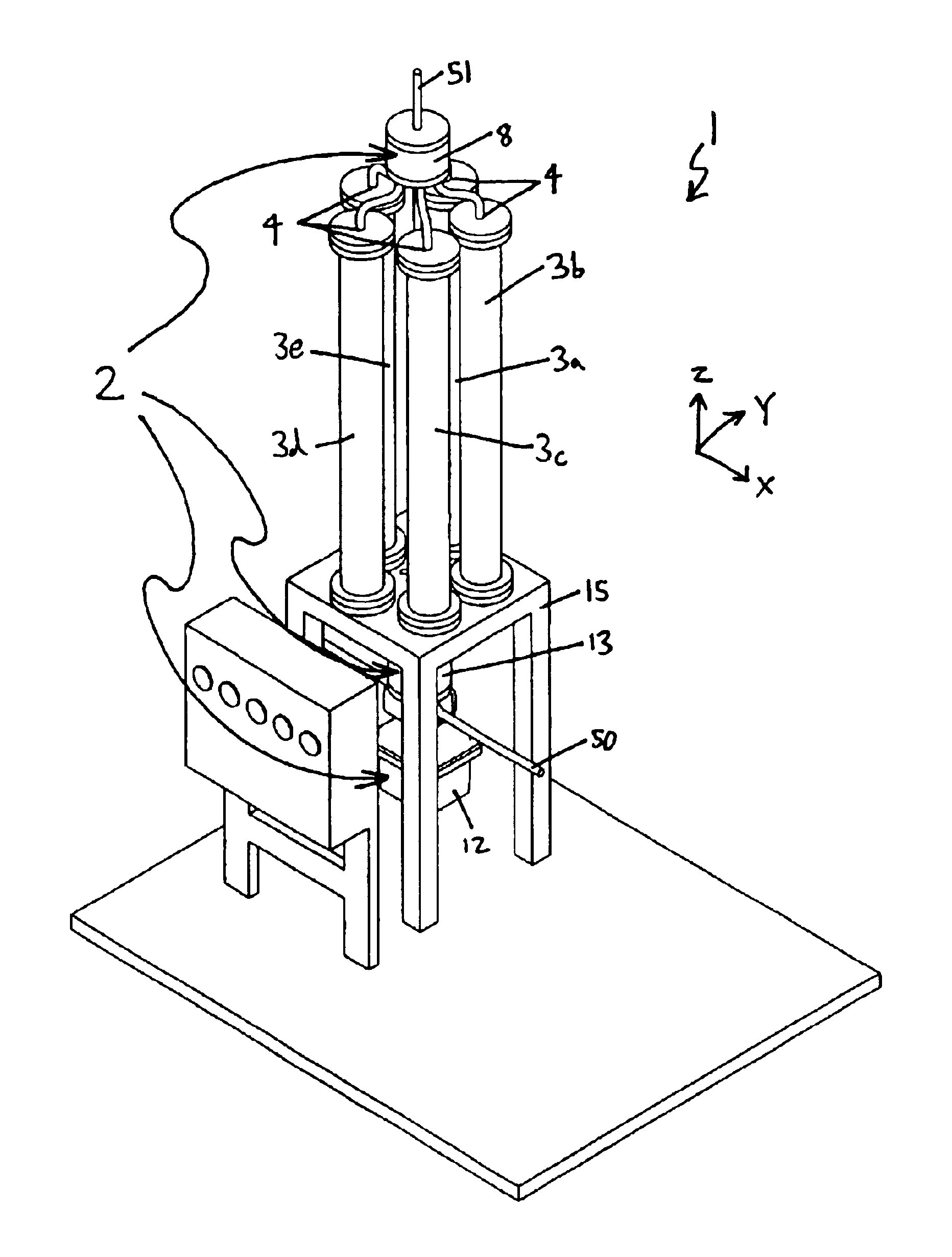
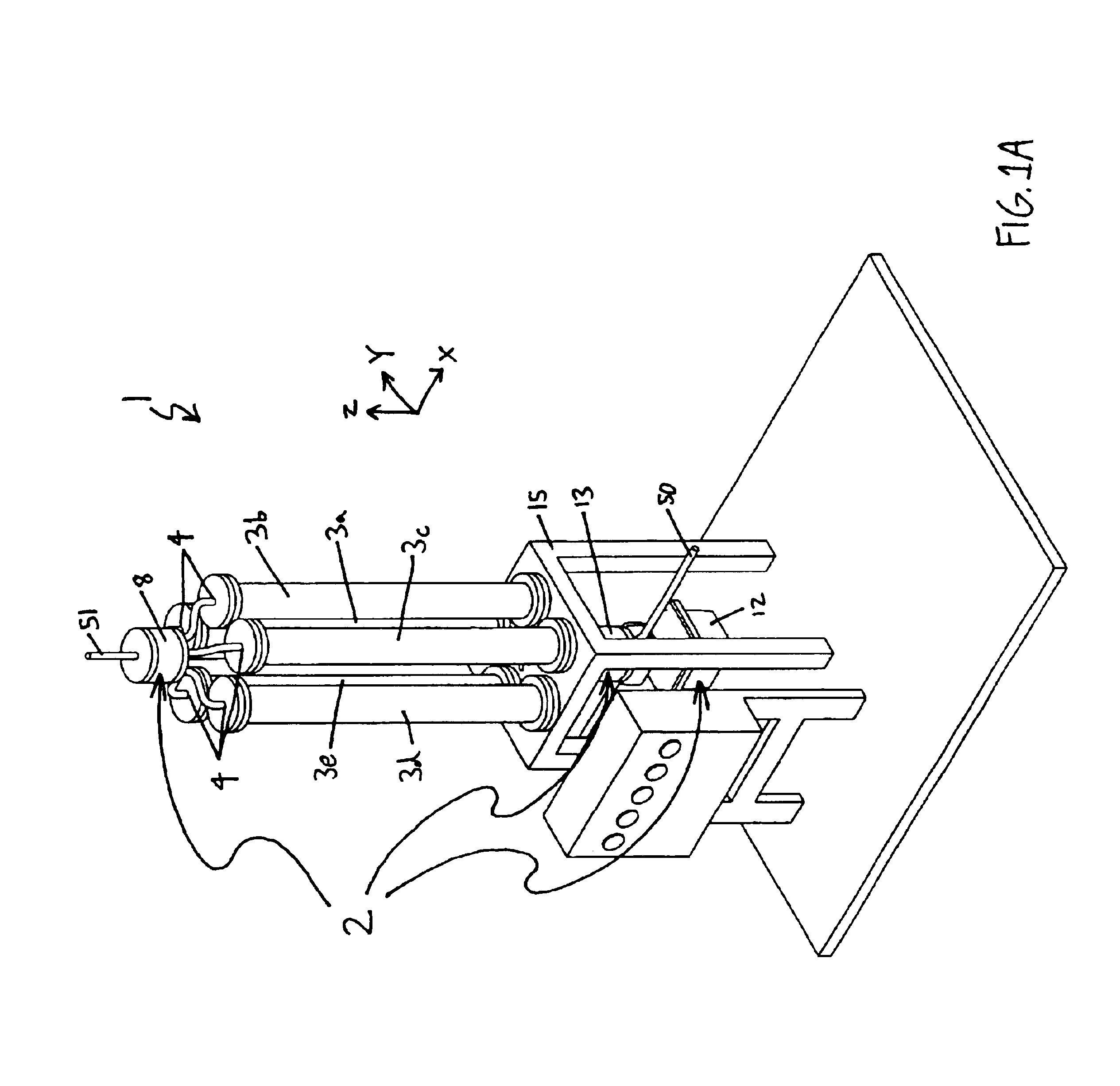
[0025]Referring now to the drawings, where like reference numeral designations identify the same or corresponding parts throughout the several views, several embodiments of the present invention are next described.

[0026]FIGS. 1A and 1B illustrate a fluid treatment system 1, which can be used in a variety of fluid treatment applications. For example, the fluid treatment system 1 can be used to treat fluids in gas form (e.g., air or natural gas) or in liquid form, depending on the functions of vessels 3a-3e included in the fluid treatment system 1. For example, each one of the vessels 3a-3e in the fluid treatment system 1 can include adsorption material adapted for hydrogen purification. Moreover, the fluid treatment system 1 can be used in a wide range of temperature and pressure operating conditions.

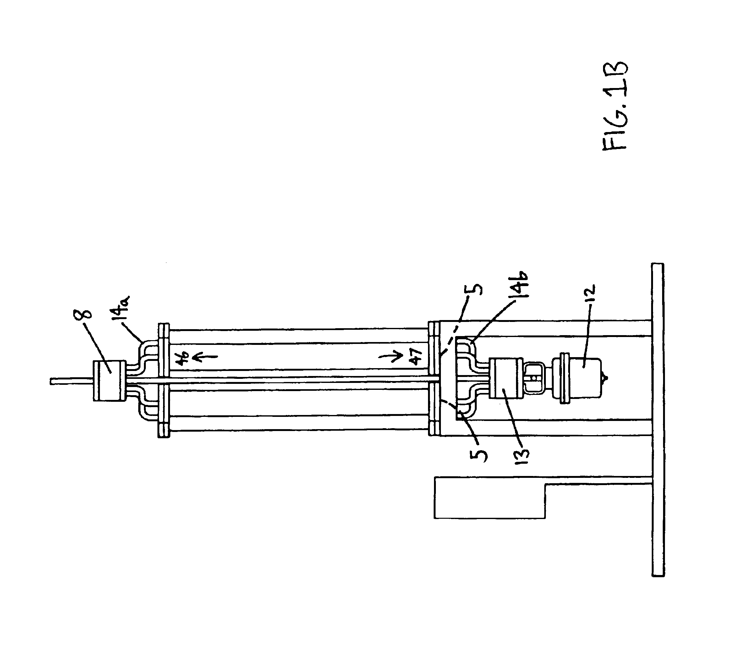
[0027]The fluid treatment system 1 includes the vessels 3a-3e and a valve assembly 2. The valve assembly 2 includes a first valve element 8, a second valve element 13, and a driving unit...


PUM

PropertyMeasurementUnit
fluid flow rateaaaaaaaaaa
purityaaaaaaaaaa
pressureaaaaaaaaaa

Abstract

A valve assembly for use in a gas purification system having a plurality of vessels each having a first port opening and a second port opening. The gas purification system includes a first valve element having a first aperture to selectively connect a first port opening of a vessel to an outlet of the first valve element. The gas purification system also includes a second valve element having a second aperture to selectively connect a second port opening of a vessel to an input of the second valve element. Also provided are a motor adapted to rotate continuously and a converting mechanism that converts continuous movement of the motor into intermittent movement. The first and second valve elements are intermittently moved by the motor and the converting mechanism such that the intermittent movement changes the vessel connected to the second aperture and the vessel connected to the first aperture.

Description

FIELD OF THE INVENTION[0001]The invention relates to fluid treatment systems and particularly to a multi-port valve assembly that can be provided in a fluid treatment system. The invention can be particularly advantageous for gas purification or gas separation, for example, to provide a hydrogen source.BACKGROUND OF THE INVENTIONDiscussion of Background[0002]Fluid treatment systems typically require one or more valves or valving systems in order to control the fluid flow, turn the flow on and off, and / or change the flow paths between and among components in the fluid system. One fluid system that will become of increasing importance is a system for the separation or purification of hydrogen, so that pure or substantially pure hydrogen can be used as an alternative to conventional fuels such as gasoline. For example, environmental and preservationist concerns have resulted in the gradual rejection of fossil fuels as the primary energy source of the future. Consequently, different met...

Claims


Application Information

Patent Timeline
Patent Type & Authority Patents(United States)
IPC IPC(8): B01D53/047B01D53/04F16K11/074F16K31/04
CPCB01D53/0446B01D53/047F16K11/074F16K31/047B01D53/053B01D53/261B01D2253/102B01D2253/108B01D2253/112B01D2256/16B01D2257/30B01D2257/702B01D2257/80B01D2258/0208B01D2259/40005B01D2259/40007B01D2259/40077B01D2259/4061
Inventor BAYREUTHER, DAVID
Owner METSO FLOW CONTROL USA INC
Why Eureka
Try Eureka