
Air/particle separator

a technology of air/particle separator and separator, which is applied in the field of separators, can solve the problems of filter clogging and needing cleaning and/or replacement, and achieve the effects of reducing the number of parts

Inactive Publication Date: 2005-08-30
NORTH JOHN HERBERT
View PDF37 Cites 31 Cited by
  • Summary
  • Abstract
  • Description
  • Claims
  • Application Information

AI Technical Summary

Benefits of technology

[0005]It is an object of the present invention to provide an improved method and apparatus for separating fine particles from a flow of a gaseous mixture such as air, or a fluid, established by suction.
[0009]1) introducing air tangentially into the chamber near the said one end thereof, the tangential entry in combination with an unapertured region of the wall of the central member establishing a rotating mass of air in the chamber, thereby causing heavier than air particles to migrate to the outer regions of the chamber under centrifugal force;
[0020]Preferably a skirt extends from the end of the central member beyond the region containing the openings in the wall hereof, to define a narrow annular gap between the it and the wall of the chamber, so that particles in the dust collecting region which due to turbulence may rise up in the region towards the central member, are prevented from reaching the openings therein unless they migrate radially outwardly to pass through the narrow annular gap against the flow of the incoming particles.
[0050]In all embodiments of the third stage an apertured sleeve or gauze preferably surrounds at least part of the central member in the third stage, to reduce the chance of particles which have been deflected therethrough from returning to leave the third stage via the first outlet.

Problems solved by technology

These filters will eventually become clogged and have to be cleaned and / or replaced.

Method used


Image

  • Air/particle separator
  • Air/particle separator
  • Air/particle separator

Examples


Embodiment Construction

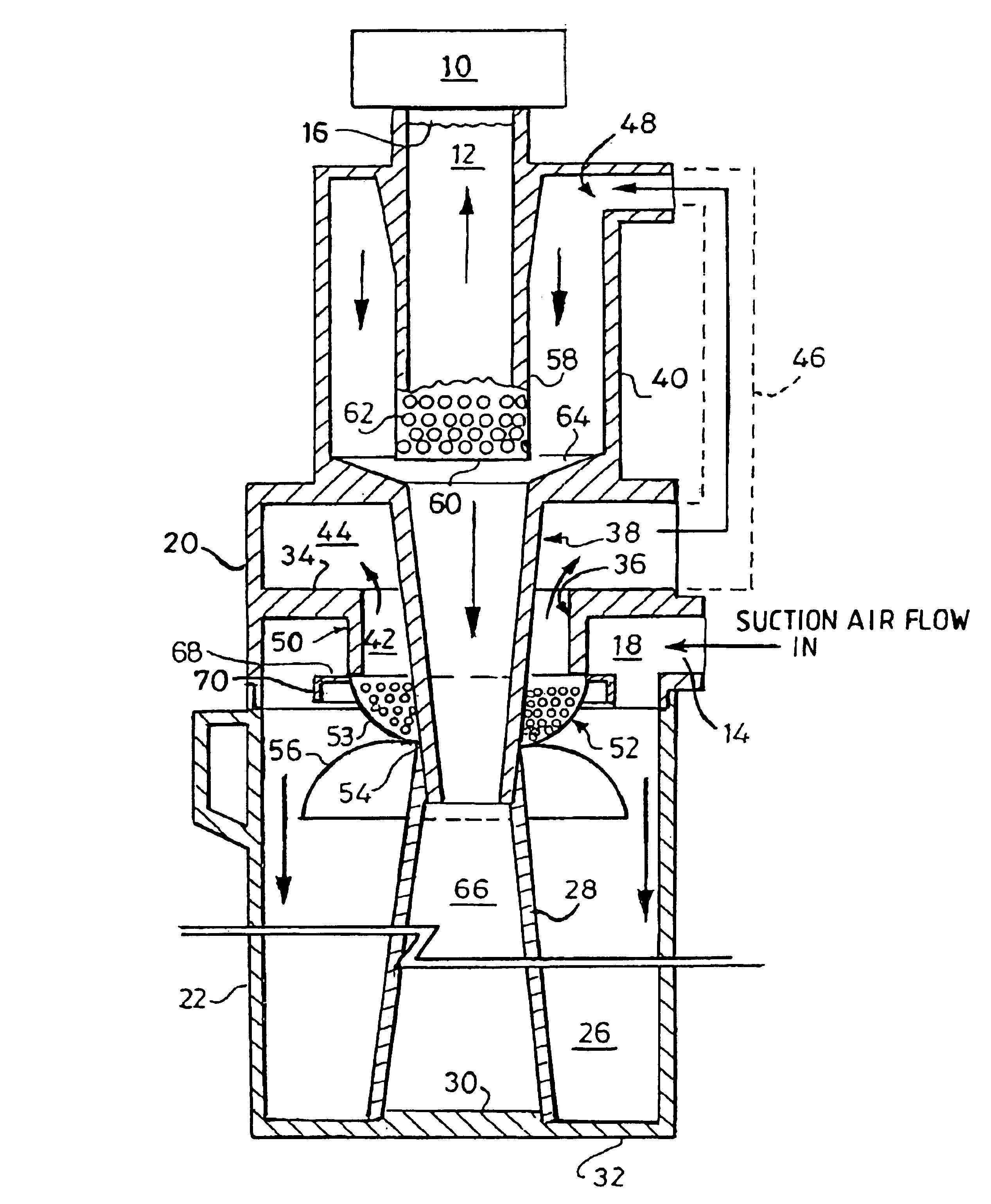
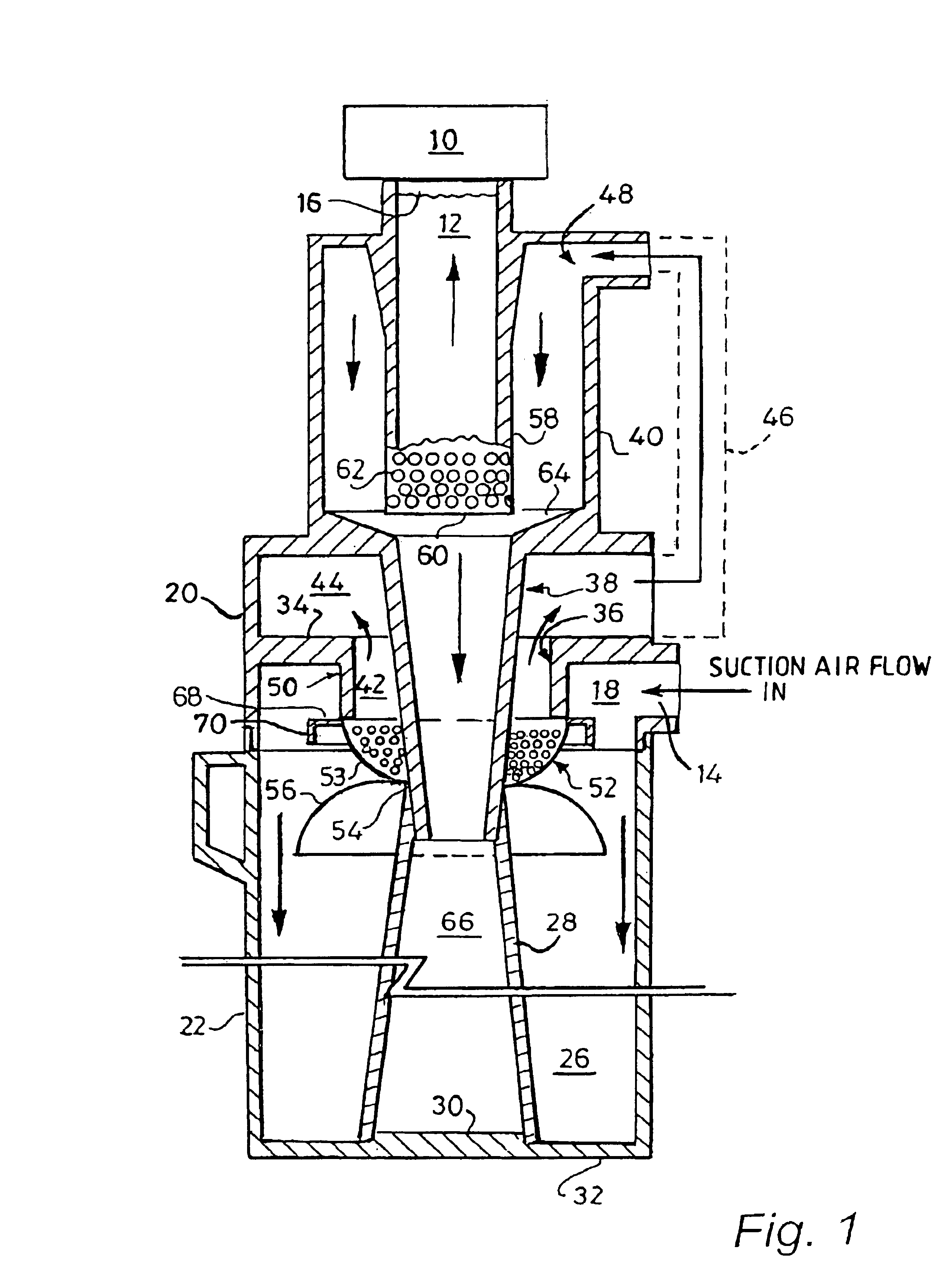
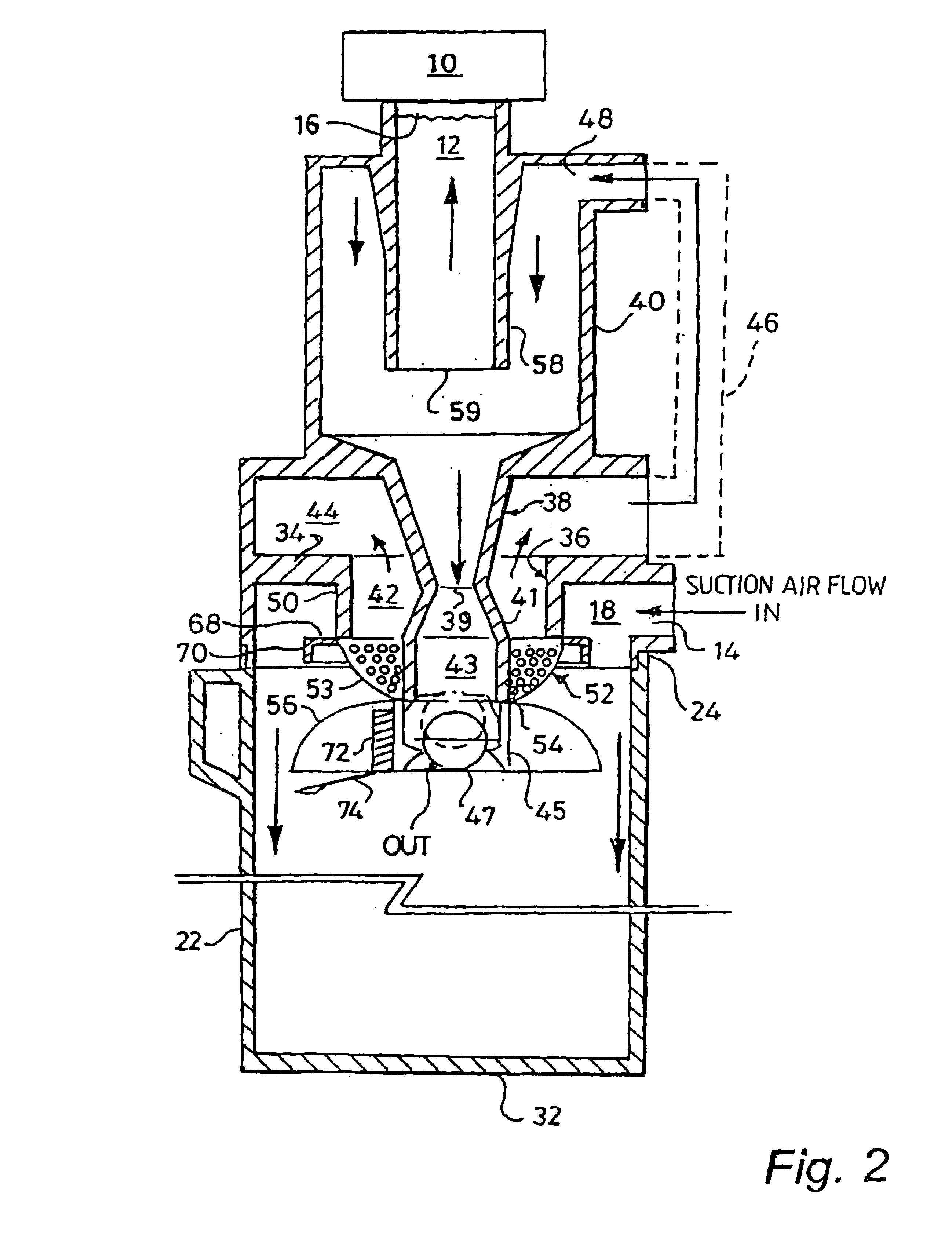
[0089]In FIG. 1 an electric motor driven fan or turbine 10 provides a source of suction at the upper end of passage 12 to draw air through the different stages of the apparatus, as will be described, from an inlet passage 14.

[0090]In the case of a domestic or commercial vacuum cleaner 14 will be connected to a hose (not shown) having a dust collecting head of known design (not shown) at its far end. The last part of the hose may in known manner be rigid.

[0091]In the case of a device for separating particles from air from apparatus such as in a laboratory or industrial or commercial environment, the inlet 14 will be connected to the enclosure from which dust / particle laden air is to be extracted.

[0092]A filter 16 (which may be removable for cleaning or replacement) may be located immediately prior to the suction source 10, although in some embodiments this may be dispensed with in view of the very high efficiency of such embodiments at removing particles from the incoming air.

[0093]T...


PUM

PropertyMeasurementUnit
Angleaaaaaaaaaa
Massaaaaaaaaaa
Diameteraaaaaaaaaa

Abstract

A method of separating particles from particle laden air having a multiple stage separator in which the first stage comprises a generally cylindrical chamber having a hollow central member extending axially from one end thereof with openings in its wall remote from the one end. The first separation step is achieved by introducing air tangentially into the chamber near its one end, establishing a rotating mass of air in the chamber causing heavier than air particles to migrate to the outer regions of the chamber. Suction is applied to the interior of the central member to cause an axial movement of air through the chamber such that particles near the walls of the chamber tend to continue in a generally rotational and axially progressive path into a particle collecting region of the chamber, while relatively particle-free air is drawn radially inwardly.

Description

FIELD OF THE INVENTION[0001]The invention concerns separators which separate one material from another based on their relative densities. In a domestic context a cyclone-based vacuum cleaner is a separator for separating dirt and dust particles from air. Similar devices are employed in industrial and commercial processes, in laboratories and in clinical and hospital environments for separating particulate material from fluids—normally air or gaseous mixture; particulate material from liquids; or one liquid from another. In particular, but not exclusively the invention is applicable to vacuum cleaners in which one or more cyclones are set up within the apparatus for the purpose of efficiently separating dust and dirt particles from an incoming airstream.BACKGROUND OF THE INVENTION[0002]Various designs of vacuum cleaner have been developed over the years. The conventional cleaner draws dust laden air through a cloth or paper container in which all particles larger than the pore size o...

Claims


Application Information

Patent Timeline
IPC IPC(8): A47L9/16A47L9/19A47L9/10B01D45/16B01D45/12B01D45/14B04C11/00B04C5/30B04C7/00B04C5/185B04C5/103B04C5/13B04C3/04B04C3/00B04C5/26B04C5/15B04C5/00
CPCA47L9/1608A47L9/1625A47L9/165A47L9/1658A47L9/19B01D45/12B01D45/14B01D45/16B04C3/00B04C3/04B04C5/103B04C5/13B04C5/15B04C5/185B04C5/26B04C5/30B04C7/00B04C11/00Y10S55/03
Inventor NORTH, JOHN HERBERT
Owner NORTH JOHN HERBERT
Learn More