
Twist-N-Lock wafer area pressure ring and assembly for reducing particulate contaminant in a plasma processing chamber

a plasma processing chamber and pressure ring technology, applied in the direction of vacuum evaporation coating, plasma technique, coating, etc., can solve the problems of increasing the chance of ring damage, reducing the time of replacement of components, and reducing the ergonomic safety of removal and reinstallation of wap ring assemblies

Active Publication Date: 2005-08-30
LAM RES CORP
View PDF12 Cites 39 Cited by
  • Summary
  • Abstract
  • Description
  • Claims
  • Application Information

AI Technical Summary

Benefits of technology

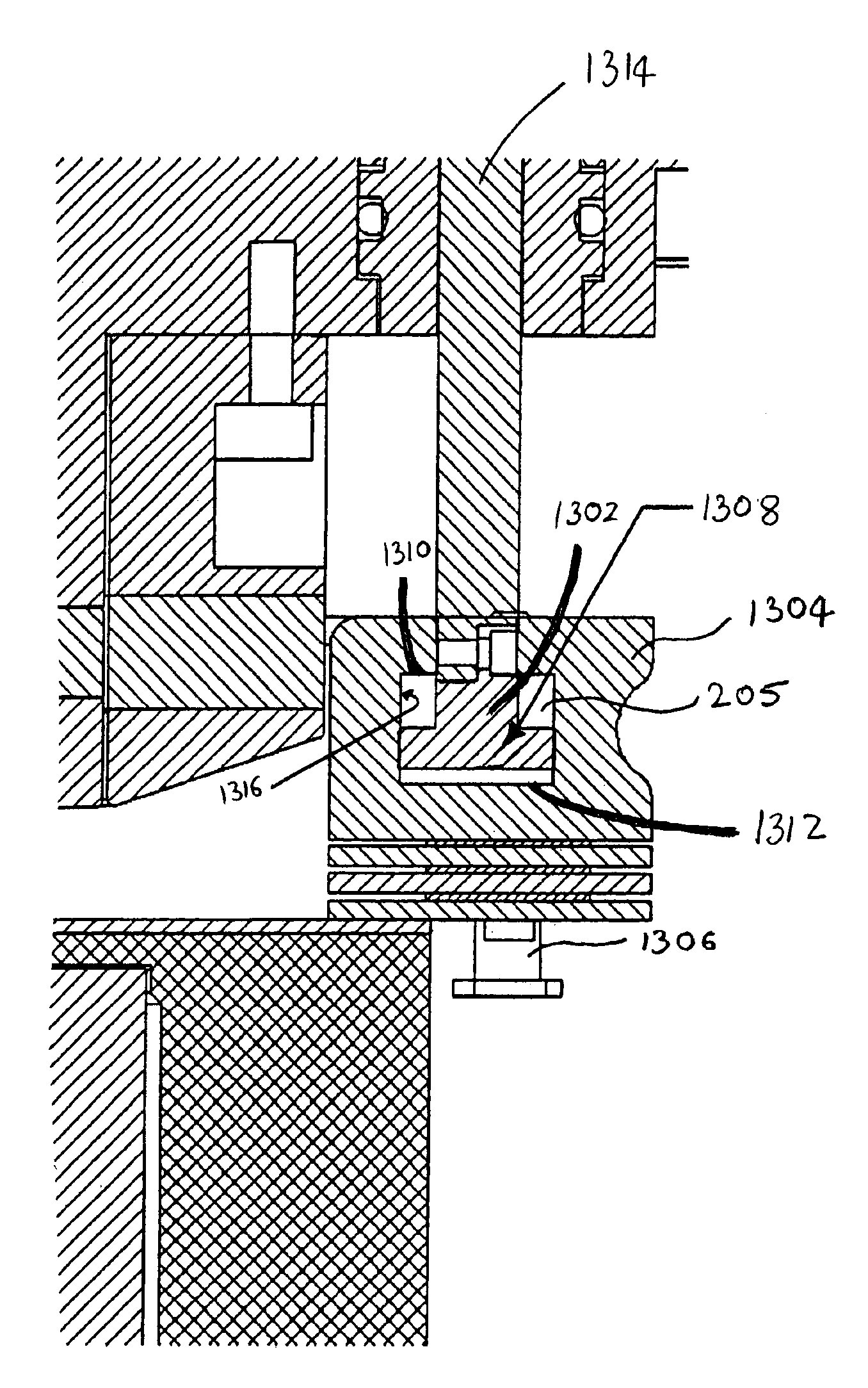
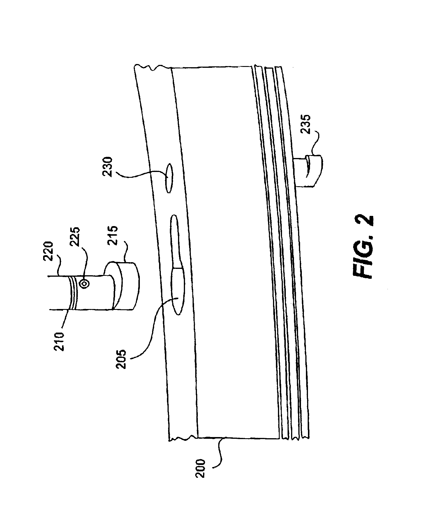
[0009]The invention relates, in one embodiment, to a confinement ring coupling arrangement for coupling, in a plasma processing chamber, a confinement ring to a plunger. The plunger is configured to move the confinement ring to deploy and stow the confinement ring to facilitate processing of a substrate within the plasma processing chamber. The confinement ring coupling arrangement includes a hanger adapter having a locking head, the hanger adapter being configured to be coupled with the plunger. The confinement ring coupling arrangement further includes a hanging bore disposed in the confinement ring and configured to receive the locking head and to secure the locking head within the hanging bore during stowing and deployment of the confinement ring, wherein a diameter of the locking head is sufficiently smaller than a cross-section dimension of the hanging bore to prevent a sidewall of the locking head from scraping against a sidewall of the hanging bore during the stowing and deployment of the confinement ring.

Problems solved by technology

The operation of removing and reinstalling the WAP ring assembly has been identified as an ergonomic safety issue.
Additionally, the use of tools and fasteners in conjunction with the installation and removal of the WAP rings increases the opportunity for ring damage, dropping of parts (e.g., screws and washers) into the pump, as well as an increased time component for replacement.
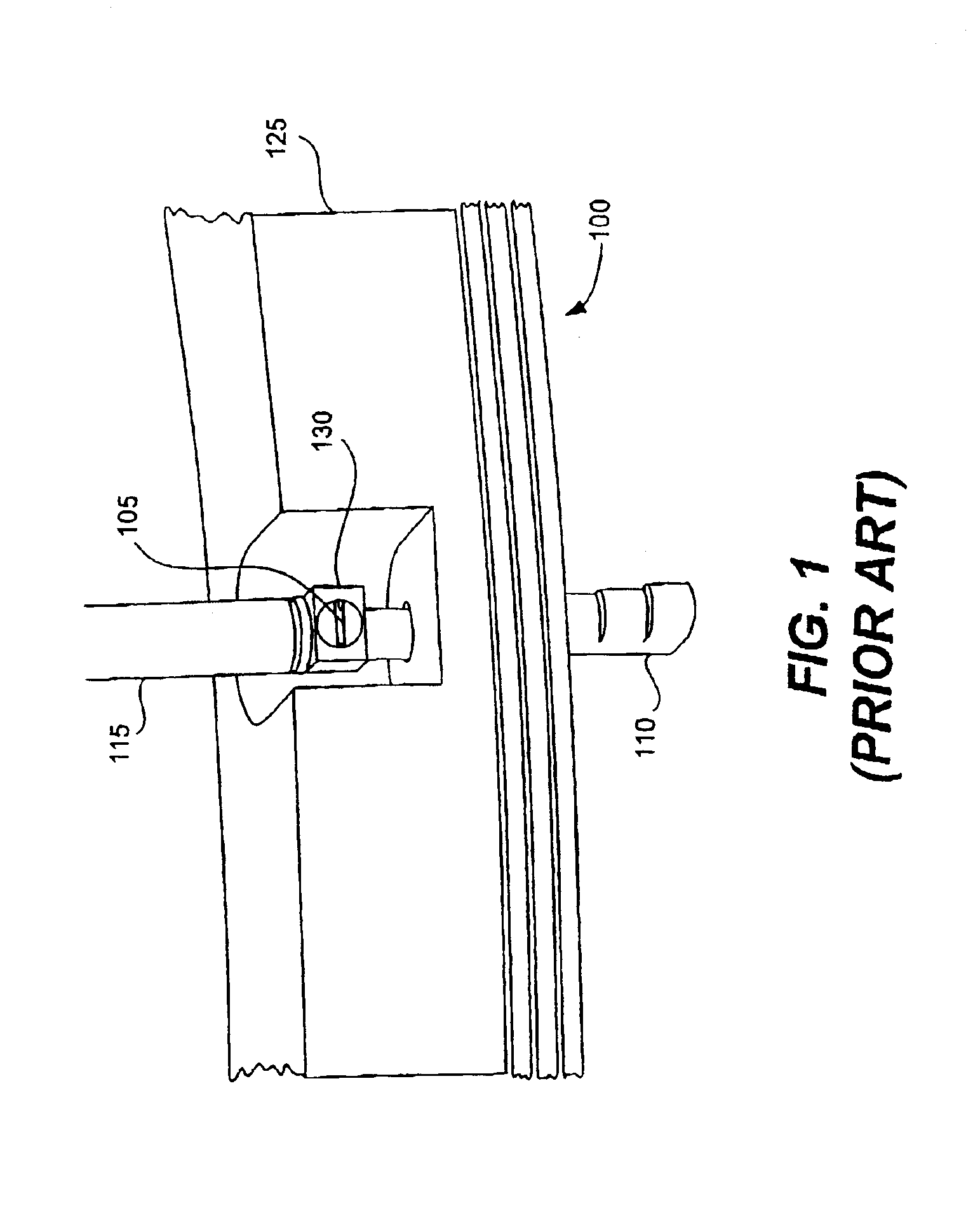
The combined hanger / stepped hanger design of the prior art is also unwieldy because while the technician is attaching the hanger to the plunger shaft, the quartz rings are loosely floating and must be securely held while the technician secures the screw 105 to the plunger shaft 115.

Method used


Image

  • Twist-N-Lock wafer area pressure ring and assembly for reducing particulate contaminant in a plasma processing chamber
  • Twist-N-Lock wafer area pressure ring and assembly for reducing particulate contaminant in a plasma processing chamber
  • Twist-N-Lock wafer area pressure ring and assembly for reducing particulate contaminant in a plasma processing chamber

Examples


Embodiment Construction

[0036]The present invention will now be described in detail with reference to a few preferred embodiments thereof as illustrated in the accompanying drawings. In the following description, numerous specific details are set forth in order to provide a thorough understanding of the present invention. It will be apparent, however, to one skilled in the art, that the present invention may be practiced without some or all of these specific details. In other instances, well known process steps and / or structures have not been described in detail in order to not unnecessarily obscure the present invention. The features and advantages of the present invention may be better understood with reference to the drawings and discussions that follow.

[0037]The present invention will now be described in detail with reference to a few preferred embodiments thereof as illustrated in the accompanying drawings. In the following descriptions, numerous specific details are set forth in order to provide a th...


PUM

PropertyMeasurementUnit
Pressureaaaaaaaaaa
Diameteraaaaaaaaaa
Shapeaaaaaaaaaa

Abstract

A confinement ring coupling arrangement for coupling, in a plasma processing chamber, a confinement ring to a plunger. The plunger is configured to move the confinement ring to deploy and stow the confinement ring to facilitate processing of a substrate within the plasma processing chamber. The confinement ring coupling arrangement includes a hanger adapter having a locking head, the hanger adapter being configured to be coupled with the plunger. The confinement ring coupling arrangement further includes a hanging bore disposed in the confinement ring and configured to receive the locking head and to secure the locking head within the hanging bore during stowing and deployment of the confinement ring, wherein a diameter of the locking head is sufficiently smaller than a cross-section dimension of the hanging bore to prevent a sidewall of the locking head from scraping against a sidewall of the hanging bore during the stowing and deployment of the confinement ring.

Description

CROSS REFERENCE TO RELATED APPLICATION[0001]The present invention claims priority from a commonly assigned U.S. Provisional Application Ser. No. 60 / 373,491, filed Apr. 17, 2002 entitled “WAP Ring Assembly Hanger Apparatus” and a commonly assigned U.S. patent application Ser. No. 09 / 916,784, filed Jul. 27, 2001 entitled “Twist-N-Lock Wafer Area Pressure Ring and Assembly”, and a commonly assigned U.S. Provisional Application Ser. No. 60 / 281,049, filed Apr. 2, 2001 entitled “Twist-N-Lock Wafer Area Pressure Ring and Assembly” all of which are by inventor Jerrel K. Antolik and are incorporated by reference herein.BACKGROUND OF THE INVENTION[0002]The present invention relates to methods and apparatus used to control the pressure around and above a substrate. More particularly, the present invention relates to improved wafer area pressure control rings.[0003]In the fabrication of semiconductor-based devices (e.g., integrated circuits) layers of material may alternately be deposited onto ...

Claims


Application Information

Patent Timeline
IPC IPC(8): H01L21/67H01J37/32H01L21/687H01L21/00
CPCH01J37/32642H01L21/67069H01L21/68728H01L21/68735Y10S156/915
Inventor ANTOLIK, JERREL K.
Owner LAM RES CORP
Learn More