Coating method and apparatus

Inactive Publication Date: 2005-08-30
IONEDGE CORP
View PDF34 Cites 20 Cited by
  • Summary
  • Abstract
  • Description
  • Claims
  • Application Information

AI Technical Summary

Benefits of technology

[0023]The main aspect of the present invention is employment of a relatively simple method and apparatus of controlled current switching emp

Problems solved by technology

The magnetic fields that were meant to control cathode spot movement we

Method used


Image

  • Coating method and apparatus
  • Coating method and apparatus
  • Coating method and apparatus

Examples


Embodiment Construction

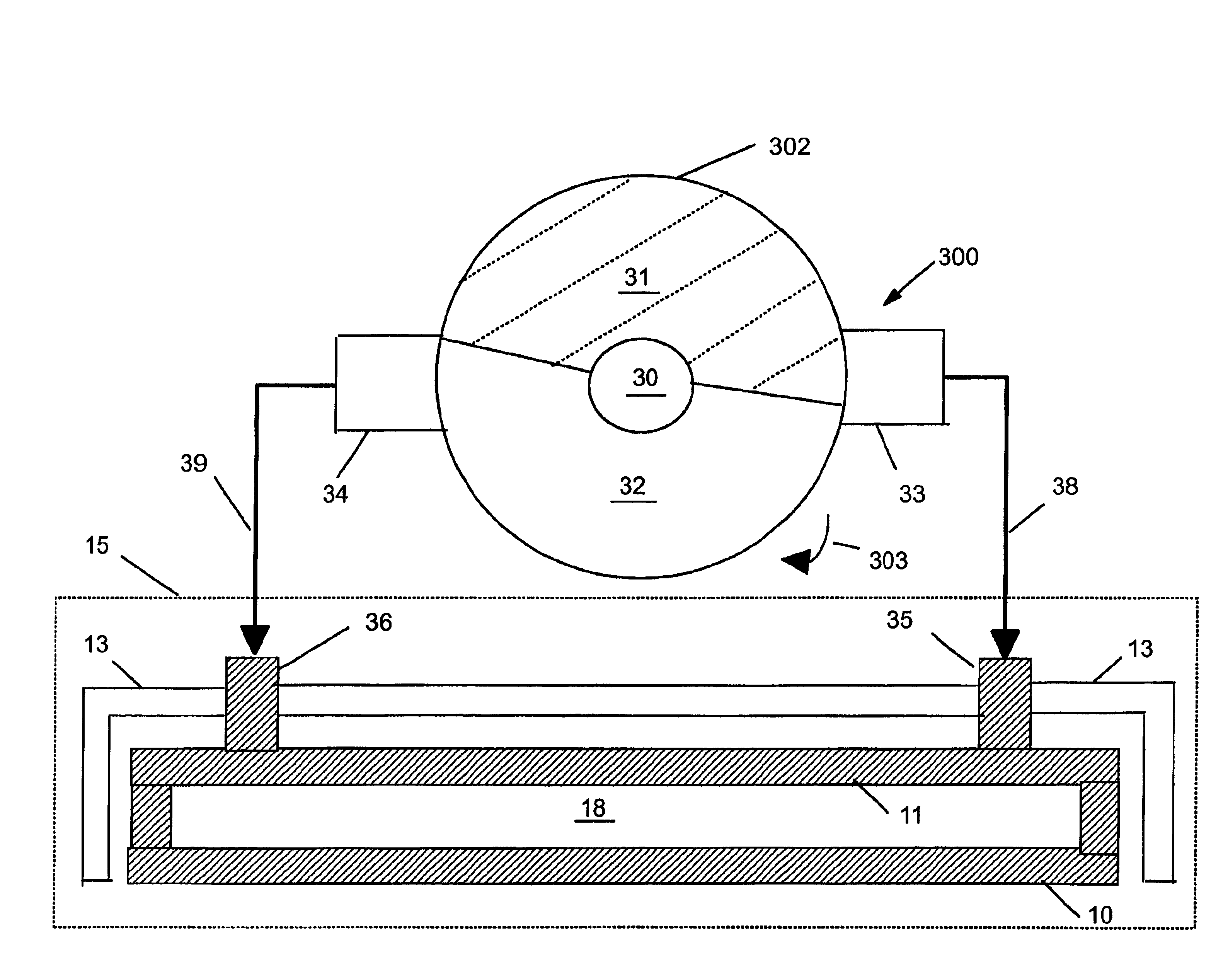
[0046]The present invention employs an external device that provides a method of current switching (toggling) to steer the arc between desired contact points of the cathode(s). As the current switching occurs, the power is transferred from one cathode lead (electrical contact point) to another cathode lead, each cathode lead being separated from the other as desired. The toggle switch toggles current between different contact points on the cathode. The benefit of this switch is to control the starting point of the arc and thus be able to move the arc in a relatively controlled manner allowing for even target wear. The wear achieved is superior to prior art resulting in better utilization and lower cost of the target material. In addition, the arc can be made to travel faster with the toggle speed as desired.

[0047]The basic implementation of the toggle switch of the present invention has many different aspects. It is first necessary to discuss the benefits of the toggle switch in com...


PUM

PropertyMeasurementUnit
Speedaaaaaaaaaa
Currentaaaaaaaaaa
Electrical conductoraaaaaaaaaa

Abstract

A method and apparatus used for the application of plating/coating in a cathodic arc process to improve coating uniformity, deposition rates, quality, cost, packaging, arc triggering, target wear and other improvements is described in the patent. The process improvements utilize a cathode with external current switching to two or more electrical cathode contacts, employment of magnets on the backside of the cathode, a non-mechanical arc initiation trigger, patterned target surfaces, adjustable cathode insulation, current modulation, and new packaging schemes.

Description

FIELD OF THE INVENTION[0001]The present invention relates to an improved method and apparatus for the application of coatings using a cathodic arc process. The process utilizes a cathode that uses external current switching, improvements in the cathode design and assembly, current switching means, new arc-striker design, adjustments for even target erosion, low frequency pulsed arc and waste reduction.BACKGROUND OF THE INVENTION[0002]Arc evaporation techniques for physical vapor deposition have been long known in the vacuum coating industry. This coating technique employs an electric arc, wherein an arc is intentionally struck on a material to be vaporized, i.e. target, and the resultant electrical energy contained in the arc then vaporizes the material, thus creating a vapor stream. The elements present in such apparatus can be generalized to include an electrically biased coating “target” material, which serves as one electrode (usually the cathode). Another portion of the deposit...

Claims


Application Information

Patent Timeline
IPC IPC(8): C23C14/32H01J37/32
CPCC23C14/325H01J37/32055H01J37/32577
Inventor SUNTHANKAR, MANDAR B.STOREY, DANIEL M.
Owner IONEDGE CORP
Why Eureka
Try Eureka