Testing electrical integrity of electrically heated subsea pipelines

a technology of electrical integrity and subsea pipelines, which is applied in the direction of pipe heating/cooling, instruments, mechanical equipment, etc., can solve the problems of difficult removal, severe viscosity increase of some crude oils, and ineffective deep water hydrate removal methods that work in shallow waters

a technology of electrical integrity and subsea pipelines, which is applied in the direction of pipe heating/cooling, instruments, mechanical equipment, etc., can solve the problems of difficult removal, severe viscosity increase of some crude oils, and ineffective deep water hydrate removal methods that work in shallow waters

US6937030B2Inactive Publication Date: 2005-08-30SHELL USA INC

Image

  • Testing electrical integrity of electrically heated subsea pipelines
  • Testing electrical integrity of electrically heated subsea pipelines
  • Testing electrical integrity of electrically heated subsea pipelines

Examples


Embodiment Construction

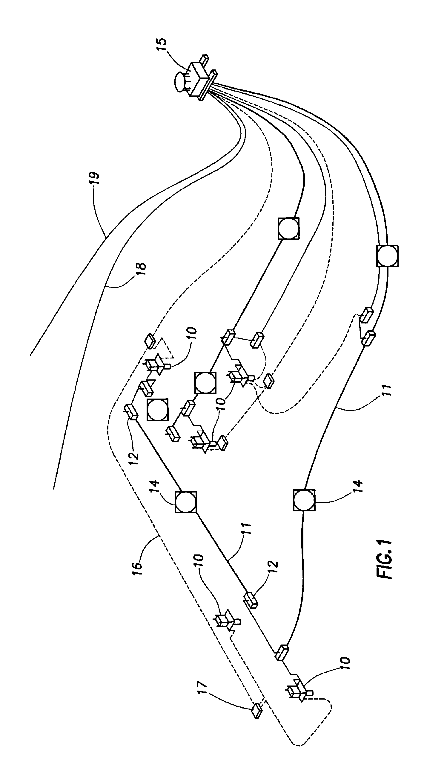
[0022]FIG. 1 illustrates subsea equipment in an oil or gas field with subsea wells producing to an offshore platform. Wellheads 10 of producing wells are connected to a segment 11 of a pipeline or flowline. Each segment 11 is terminated at each end at sled 12, where a bulkhead is present between the inner and outer pipe. Approximately mid-way along each segment 11 is Mid-Line Electrical Connector (MLEC) 14, which is described below. Segments of a pipeline join and transport fluid from wellheads 10 to platform 15. Control lines 16 from platform 15 are connected to controllers 17 for each well. Fluids from platform 15 are transported to shore or other facilities through oil export line 18 and gas export line 19.

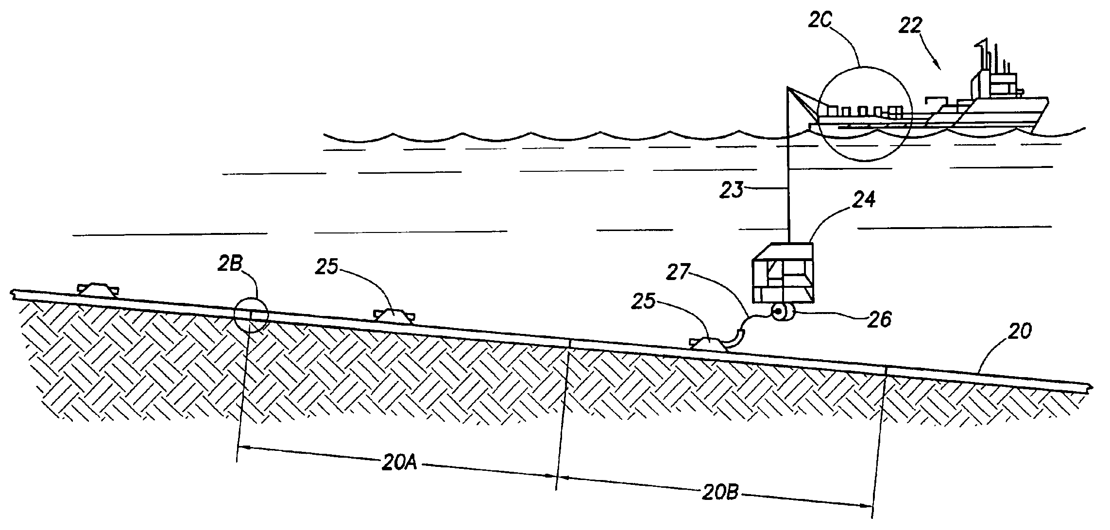
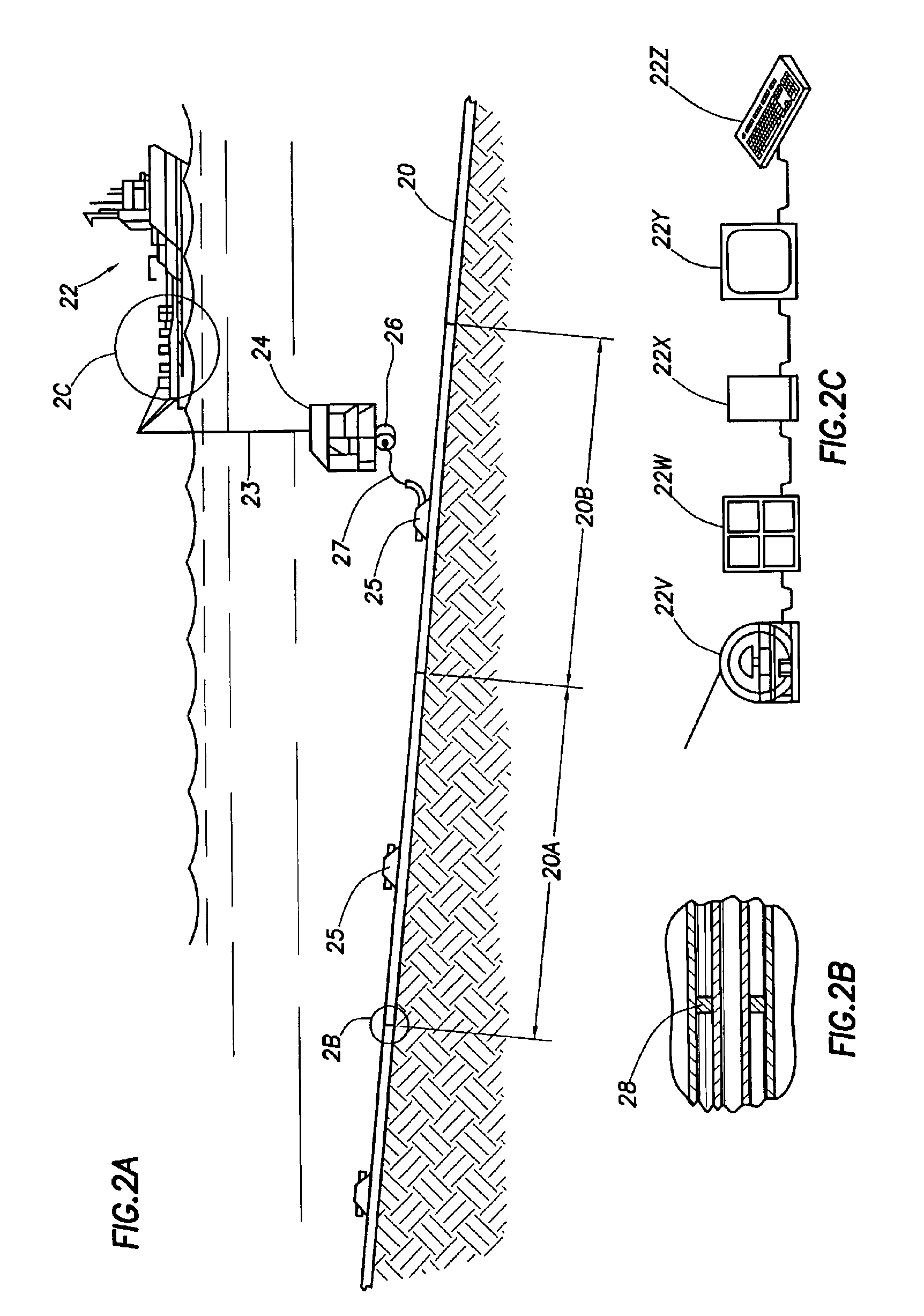
[0023]FIG. 2A illustrates a configuration of the present invention directed to subsea pipe-in-pipe pipeline 20 having segments 20A and 20B. Ship 22 has been moved in place to lower ROV 24 on umbilical 23 to the proximity of mid-line electrical connector (MLEC) 25. Canister 26, ...


PUM


Abstract

Method is provided for testing electrically heated subsea pipelines that are “electrical-ready,” that is, equipped for applying electrical power when it is needed for heating the pipeline at any time during the life of the pipeline. Time domain reflectometer apparatus in a water-tight enclosure can be deployed subsea. Electrical connections are made with the pipeline using wet-mateable connectors. Reflected signals from the segment of the pipeline being tested are transmitted to an interface at the surface, where the time domain reflectometer is controlled to send a selected pulse. Reflected signals may be interpreted by observing pulse form and time of receipt or by comparison of pulse forms received at different times during the life of a pipeline. Apparatus for electrically connecting a time domain reflectometer to an electrical-ready pipeline is provided.

Description

BACKGROUND OF THE INVENTION[0001]1. Field of the Invention[0002]The present invention relates to electrically heated subsea pipelines. More particularly, method and apparatus are provided for determining the electrical integrity of subsea pipelines that are equipped with wet-mateable subsea connectors for electrical heating of the pipeline.[0003]2. Description of Related Art[0004]Companies seeking to recover hydrocarbons offshore must often drill wells in water several thousands of feet deep. In many cases, groups of these deep wells feed recovered hydrocarbon fluids into remote platforms via lengthy underwater pipelines resting on the ocean floor. Because these subsea pipelines lay at great depths, the seawater that surrounds them has a temperature in the range of 40° F. The hydrocarbon fluids, however, usually reach the ocean floor from the wells at much greater temperatures. That is, the hydrocarbons arrive at the high temperatures near those typical of depths of thousands of fee...

Claims


Application Information

Patent Timeline
30 Aug 2005
Publication
US6937030B2
IPC
G01R31/11; G01R31/08
CPC
G01R31/11; F16L53/007; F16L53/37
Inventors
LINEY, DAVID J.; MARCH, DAVID M.