System and method for transmission-line termination by signal cancellation, and applications thereof

a transmission line and signal cancellation technology, applied in the field of electrical wired communication, can solve the problems of limiting the rate at which data can be transmitted over a transmission line, the need for termination is a major drawback in building a network, and the inability to be simpl

Inactive Publication Date: 2005-08-30
CONVERSANT INTPROP MANAGEMENT INC
View PDF4 Cites 148 Cited by
  • Summary
  • Abstract
  • Description
  • Claims
  • Application Information

AI Technical Summary

Benefits of technology

[0015]The invention relates to a system and method for signal termination, based on a two-port unit, denoted herein as a Signal Canceling Unit (SCU). The SCU senses the signal present over its terminal, and operates to absorb and cancel this signal. When connected at an end of a transmission line, such as a wire transmission line used for communication, the SCU functions as a terminator by absorbing the signal energy. When connected in the middl

Problems solved by technology

These effects, when caused by impedance mismatch, become more pronounced as the length of the conductor increases, and limit the rate at which data can be transmitted over a transmission line.
The need for termination is a major drawback in building a network.
First, the transmission line ends must be identified and accessed, which may not be simple in the case of existing wiring.
Additionally, terminator installation requires both labor and materials, and there is also the issue of additional equipment requir

Method used


Image

  • System and method for transmission-line termination by signal cancellation, and applications thereof
  • System and method for transmission-line termination by signal cancellation, and applications thereof
  • System and method for transmission-line termination by signal cancellation, and applications thereof

Examples


Embodiment Construction

[0036]The principles and operation of a network according to the present invention may be understood with reference to the drawings and the accompanying description. The drawings and descriptions are conceptual only. In actual practice, a single component can implement one or more functions; alternatively, each function can be implemented by a plurality of components and circuits. In the drawings and descriptions, identical reference numerals indicate those components that are common to different embodiments or configurations.

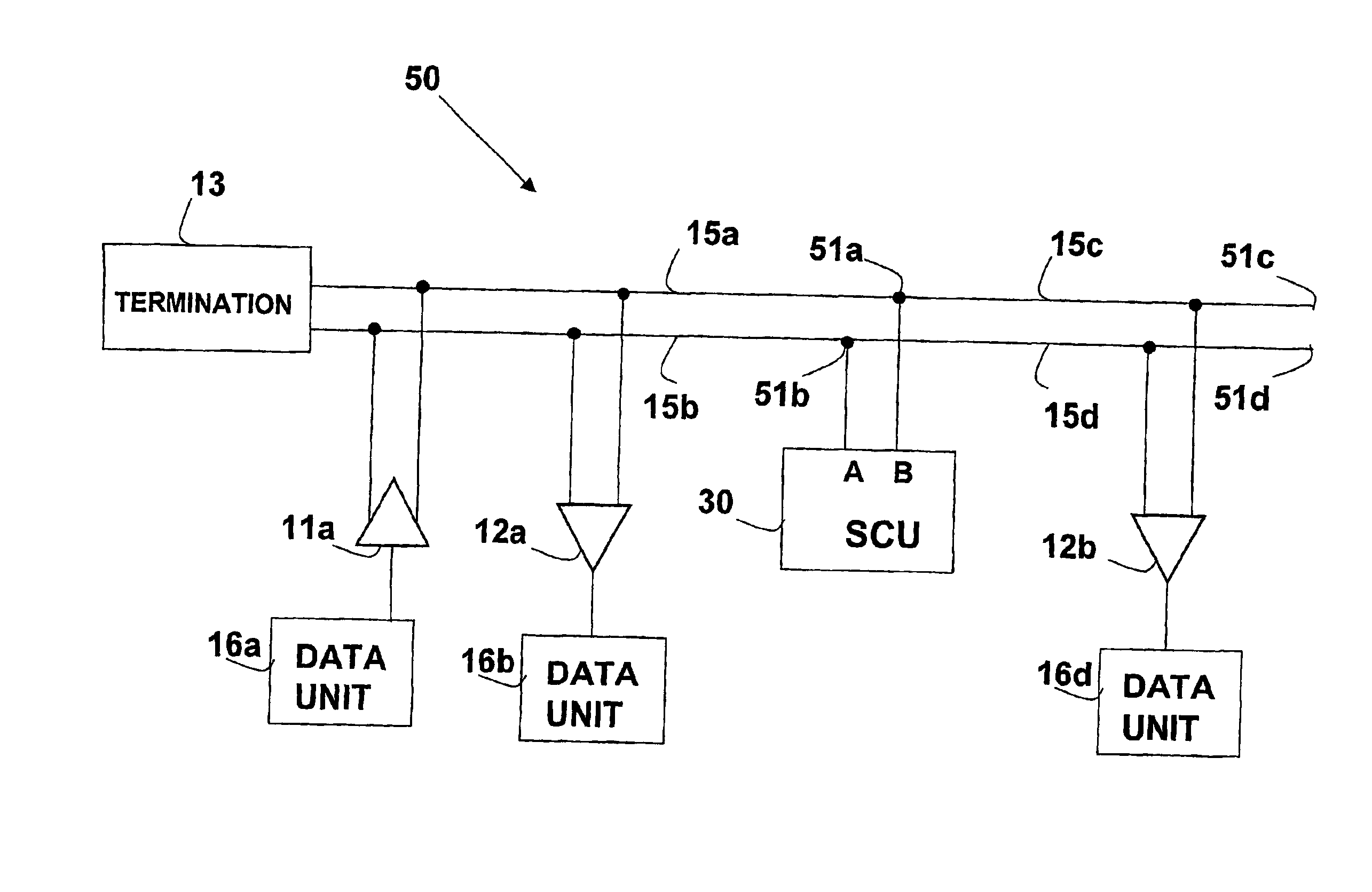
[0037]FIG. 3 illustrates a Signal Canceling Unit (SCU) 30, which includes two external terminal connections, a terminal 34a (A) and a terminal 34b (B). Coupled to these terminals is a sensor 31, which measures the differential voltage (constituting a “first signal”) between terminal 34a and terminal 34b. The value measured by sensor 31 is input into a processing unit 33, which in turn provides input to a differential driver 32 (constituting a “first driver”), w...


PUM


Abstract

An active terminating device (30) for an electrical transmission line with optional line-receiving and line-driving capabilities. The basic device is a two-terminal unit, denoted as a Signal Canceling Unit (SCU), which sensesthe signal available at its terminals (34a, 34b), and applies negative feedback in order to cancel and absorb the signal. When applied to the end of a transmission line (15a, 15b) as part of wired communication network, the SCU functions as a terminator. When connected in the middle of such wired transmission line, the SCU splits the transmission line into two separate and isolated segments. In such a configuration, the SCU can be used to isolate a portion of a network from signal degradation due to noise or bridge-tap. Furthermore, the two isolated segments may each employ independent communications, such that no interference exists between the segments. In another embodiment, line receiver functionality is integrated into the SCU, designated as a Signal Canceling and Receiving Unit (SCRU) (90). The SCRU can perform all the SCU functions, and also serves as a line receiver in the communication network. In yet another embodiment, line driver functionality is integrated into the SCRU, designated as a Signal Canceling, Receiving and Transmitting Unit (SCRTU) (120). The SCRTU can perform all the SCRU functions, and also serves as a line driver in the communication network. Upon connecting multiple SCRTU's to a continuous transmission line, terminated independent point-to-point communication segments are formed.

Description

[0001]This application is a 371 of PCT / IL01 / 00863, filed on Sep. 12, 2001.FIELD OF THE INVENTION[0002]The present invention relates to the field of electrically-wired communication, and, in particular, to communication lines employing terminationBACKGROUND OF THE INVENTION[0003]The term “data unit” herein denotes any data processing device, such as a computer or a personal computer, including workstations or other data terminal equipment (DTE) with an interface for connection to any wired communication network, such as a Local Area Network (LAN).[0004]Transmission lines over which digital signals are transmitted must be properly terminated in order to prevent overshoot, undershoot and reflections. These effects, when caused by impedance mismatch, become more pronounced as the length of the conductor increases, and limit the rate at which data can be transmitted over a transmission line. The transmission line can be a trace on an integrated circuit, a trace on a board, or a wire in a...

Claims


Application Information

Patent Timeline
IPC IPC(8): H03K19/003H03K17/16H04L5/14H04B3/20H04L25/00H04L25/02H04L27/00H04B
CPCH03K19/0005H04L5/14H04L27/0002H04L25/0272H04L25/0298H04L27/00H04L25/02H04L12/40032H04L25/00
Inventor BINDER, YEHUDA
Owner CONVERSANT INTPROP MANAGEMENT INC
Why Eureka
Try Eureka