Data source, data conversion device, inverse data conversion device, auxiliary data file generation device, reception method, medium and information aggregate

a data conversion device and auxiliary data file technology, applied in data switching networks, two-way working systems, instruments, etc., can solve the problems of inability to add inability to obtain needed data from stream data record/regeneration devices, and difficulty in adding means having functions other than those originally prepared for editing equipment. , to achieve the effect of reducing the amount of memory required

Inactive Publication Date: 2005-08-30
PANASONIC CORP
View PDF18 Cites 16 Cited by
  • Summary
  • Abstract
  • Description
  • Claims
  • Application Information

AI Technical Summary

Benefits of technology

[0112]Considering the above described first problem, the present invention intended to provide a data source, a medium and a information aggregate that reduce the amount of memory required by the PC while keeping the number of the frame buffer unchanged.

Problems solved by technology

To process / edit the video and audio recorded with the VTR, specialized edit equipment can be used, but they are expensive and it is difficult to add means having functions other than those originally prepared to the edit equipment.
That is, in a conventional data source, there is a problem (first problem) that some trade-off relationship is formed between the stability of send and the amount of memory required by the PC.
However, since data that is dealt with by the stream data record / regeneration device 2 is stream data and not a file format (namely, it does not have header information and index information), and in the PC 1, the software 4 dealing with audio / video data makes access to recording media including the HDD 7 in the first place in asynchronous timing as well as to arbitrary data, making a direct access to the stream data record / regeneration device 2 that generally performs record / regeneration in real time does not help obtain needed data.
In the case where the software 4 dealing with audio / video data only wants to process data recorded in the stream data record / regeneration device 2 and write the result in the HDD of the PC, and inversely, in the case where the software 4 dealing with audio / video data only wants to process the data in the HDD of the PC and write the result in the stream data record / regeneration device, itis similarly complicated, and HDD capacity is required.
If data can be accumulated in the HDD, it is inevitably captured by the reception and data conversion software temporarily, but data should be replaced soon because the capacity of the HDD is soon exhausted, which is very complicated.
That is, there is the problem (second problem) that procedures and devices for editing video and audio recorded in the stream data record / regeneration by PC device are complicated.
Furthermore, there is the problem (third problem) that an access cannot be made from the software editing video and audio of the PC directly to the video and audio recorded in the stream data record / regeneration device.
Furthermore, there is the problem (fourth problem) that a HDD of large capacity is required when the video and audio of the PC are edited.
Furthermore, in the conventional configuration described for the third prior art, there is the problem (fifth problem) that release of resources of the IEEE 1394 bus cannot be carried out properly and after that, these resources cannot be used if operations are performed in the order shown in FIG. 30.

Method used


Image

  • Data source, data conversion device, inverse data conversion device, auxiliary data file generation device, reception method, medium and information aggregate
  • Data source, data conversion device, inverse data conversion device, auxiliary data file generation device, reception method, medium and information aggregate
  • Data source, data conversion device, inverse data conversion device, auxiliary data file generation device, reception method, medium and information aggregate

Examples


first embodiment

[0291]To begin with, a first embodiment will be described using FIG. 1 to FIG. 9.

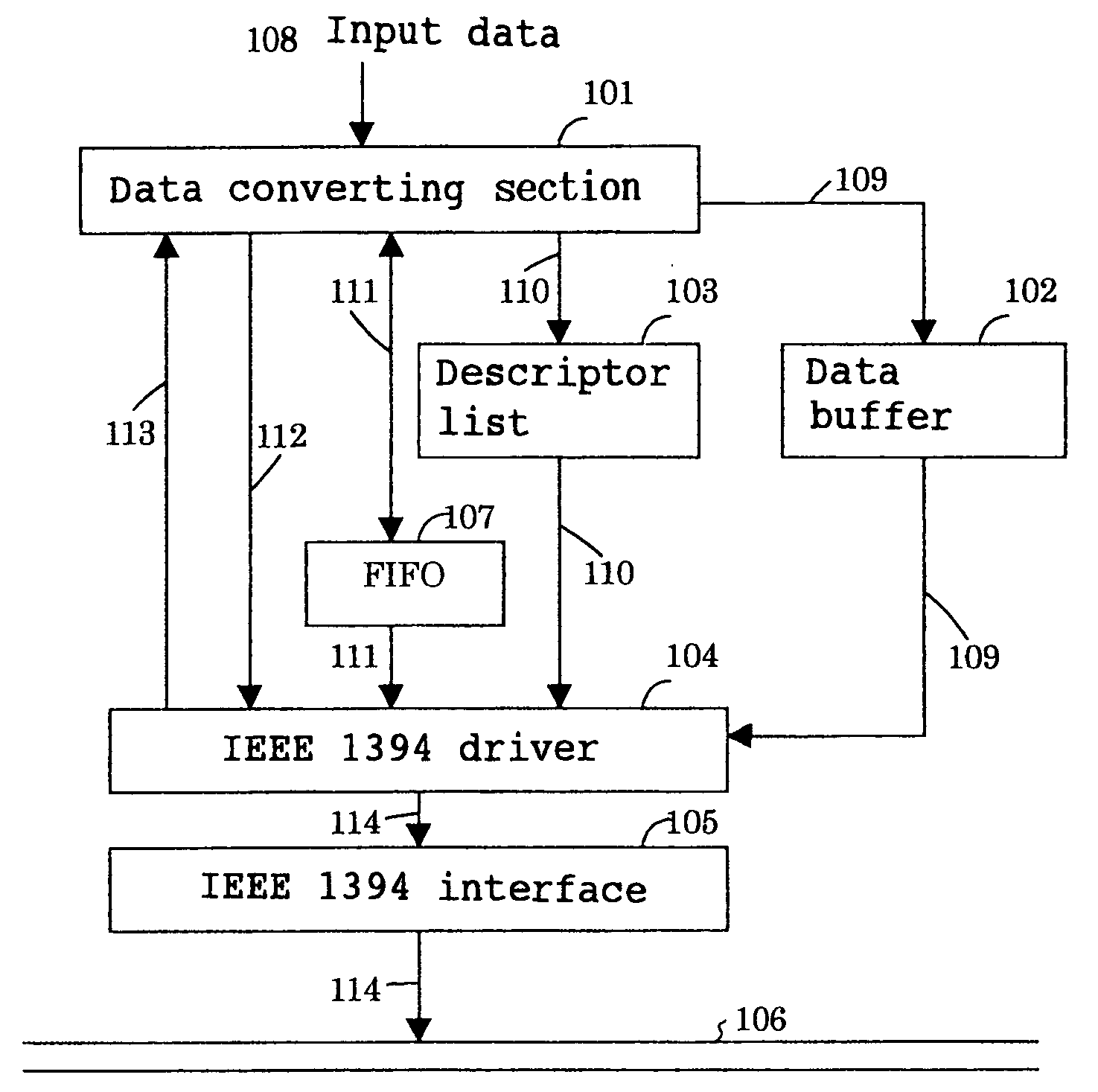
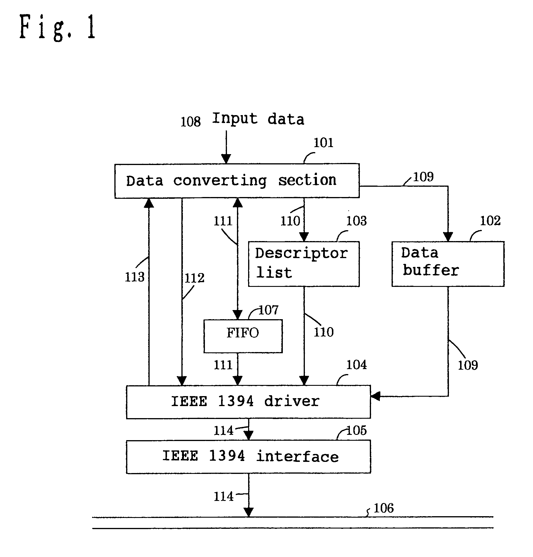
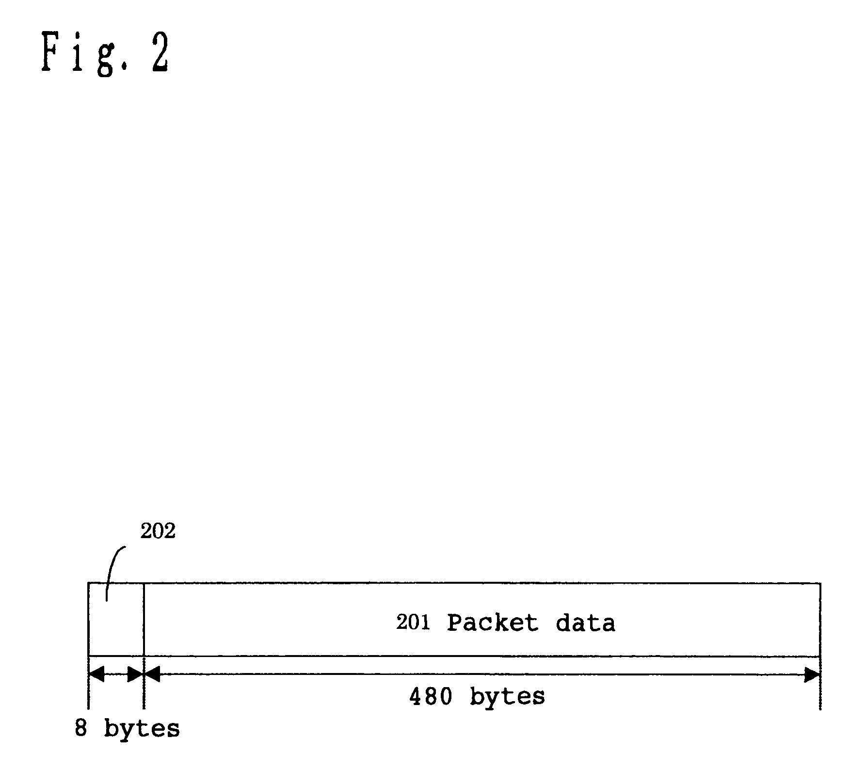
[0292]A configuration of the date source in this embodiment is similar to the first prior art, input data 108 is DV data configured by a plurality of packet data 201, and a CIP data 109 complies with IEC 61883.

[0293]FIG. 8 and FIG. 9 show one example of a FIFO 107 of a data source according to this embodiment. In FIG. 8 and FIG. 9, the addresses of a descriptor 110 which are located in the lower hierarchy of the FIFO 107, were stored later in the FIFO 107. Also, an unsent flag 502a, an unsent flag 502b, an unsent flag 502c and an unsent flag 502d are in a “already sent” or “unsent” condition, and the initial condition is set to “already sent.”

[0294]Operations of the data source according to the embodiment of the present invention having the configuration as described above will be described below.

[0295]Upon receiving input data 108, a data converting section fetches packet data 201 therefrom, adds CIP h...

second embodiment

[0312]Now, a second embodiment will be described.

[0313]FIG. 12 is a block diagram for explaining the data conversion device of the embodiment of the present invention, and data converting means 11 shown in FIG. 12 is the date conversion device of this embodiment. In FIG. 12, 12 is request analyzing means, and 13 is selecting means.

[0314]First, upon receiving a request of data read (a position from the front-end of a file and the size of data to be read) from software 4 dealing with audio / video data via software 6 managing files, the request analyzing means 12 analyzes which portion of video data, audio data, header information and index information is requested based on header information and index information prepared as a file in the HDD 7. Also, if the video data is requested, the request analyzing means 12 controls stream data record / regeneration device 2 so that a requested portion of video data can be obtained.

[0315]The selecting means 13 outputs the header information and the...

embodiment 3

[0347]Now, a third embodiment will be described using FIG. 18 to FIG. 20 and FIG. 25 to FIG. 28.

[0348]The configuration and operations of the DV 702 are similar to those of the third prior art, and the configuration of the PC 701 is similar to that of the third prior art.

[0349]Furthermore, the DV 702 of this embodiment is an example of the data source of the present invention, the PC 701 of this embodiment is an example of the personal computer of the present invention, the driver 704 for DV, IEEE 1394 driver 705 of this embodiment is an example of device controlling means of the present invention.

[0350]The operations of the PC 701 will be described.

[0351]Upon receiving start-of-reception instructions as operation instructions 714 from the application 703, the driver 704 for DV sends a request to obtain the value of the oPCR[0]708 of the DV 702 to the IEEE 1394 driver 705 as the request 715, first. The IEEE 1394 driver 705 requests the IEEE 1394 interface 709 to send the register da...


PUM


Abstract

A data source has a data converting part for converting inputted data to predetermined data packets. A data buffer stores the data packets. A descriptor list stores a descriptor to which predetermined addresses are added, where a method of sending the data packets is described. A FIFO stores the predetermined addresses in a first-in first-out mode. A data sending part receives start instructions from the data converting part, refers to a predetermined address in which reference is not made yet in the FIFO, fetches data packets corresponding to the descriptor from the data buffer in accordance with a method of sending the descriptor indicated by the predetermined address, generates a send packet from the data packet and outputs the data packet. An end-of-send notice to the data converting part is also send when the output of the send packet is ended.

Description

BACKGROUND OF THE INVENTION[0001]1. Field of the Invention[0002]The present invention relates to a data source transmitting packet data, a device and method for processing stream data to be recorded in a record / regeneration device while making the stream data look like a file, and a reception method in a data sink on an IEEE 1394 bus.[0003]2. Related Art of the Invention[0004]As LSI technology improves, networks where video information and audio information are digitized and transmitted are being developed. Since video signals and audio signals should be regenerated in real time, networks enabling real time transmission are required.[0005]As a network suitable for real time transmission like this, a network called IEEE 1394 is proposed. The IEEE 1394 is a serial high-speed bus system and is compatible with synchronous transmission, thus enabling real time transmission of data.[0006]Currently, the IEEE 1394 is installed as an external interface in digital VCRs for use at home (herein...

Claims


Application Information

Patent Timeline
Patent Type & Authority Patents(United States)
IPC IPC(8): H04L12/40H04L12/56H04L12/64G06F5/00H04L49/901
CPCH04L12/40058H04L12/40071H04L12/40117H04L49/90H04L49/901G06F5/00
Inventor YOSHIDA, JUNJIMATSUMI, CHIYOKOJURI, TATSUROYAMADA, MASAZUMI
Owner PANASONIC CORP
Why Eureka
Try Eureka