Interference-signal removing apparatus

a signal removal and interference technology, applied in the direction of amplitude demodulation, line-faulst/interference reduction, pulse technique, etc., can solve the problem of deteriorating the bit error ratio of the reception signal, attenuation of the cdma component in the reception signal, and in accordance with the attenuation progress, so as to improve the characteristic of the input signal and remove interference

Active Publication Date: 2005-08-30
KOKUSA ELECTRIC CO LTD
View PDF13 Cites 22 Cited by
  • Summary
  • Abstract
  • Description
  • Claims
  • Application Information

AI Technical Summary

Benefits of technology

[0111]In this case, it is considered that a CDMA signal is extracted simultaneously when estimating an interference signal as a reason of the above trouble. That is, this is because a CDMA signal component which does not originally have any correlation and must not be estimated by providing a time difference for one chip or more locally has a correlation due to a factor such as inter-code interference because of the influence of a ban-restriction filter and is estimated as an interference signal. Therefore, the spectrum is disarranged and the band is spread. Thus, as a result, a problem occurs that the bit error ratio of a reception signal free from interference is deteriorated. This phenomenon always occurs independently of presence or absence of an interference signal by operating an interference-signal removing apparatus for a long time and has a feature that the phenomenon more easily occurs as the power of a CDMA signal component increases. Therefore, the phenomenon remarkably occurs because the CDMA power is remarkably increased by AGC control under an environment in which no interference signal is present.
[0186]Thus, an interference-signal removing apparatus of the present invention makes it possible to improve the characteristic of an input signal when the power of a narrow-band interference signal is smaller than that of a wide-band desired signal by removing interference correspondingly to desired signals or interference signals included in input signals and moreover, flexibly removing interference every interference signal even when a plurality of narrow-band interference signals are included in input signals.

Problems solved by technology

In this case, the above trouble occurs because an adaptive filter extracts an interference signal from a reception signal and simultaneously extracts a CDMA signal and removes not only the interference signal but also a CDMA signal component.
As a result, a problem occurs that a bit error ratio of the reception signal is deteriorated after removing interference.
Moreover, the above conventional interference-signal removing apparatus has a problem that when starting interference signal removal and then still continuing the removal, the CDMA component in a reception signal is also attenuated and the attenuation progresses in accordance with the elapse of time.

Method used


Image

  • Interference-signal removing apparatus
  • Interference-signal removing apparatus
  • Interference-signal removing apparatus

Examples


first embodiment

[0219]First, an interference-signal removing apparatus of first embodiment of the present invention is described below.

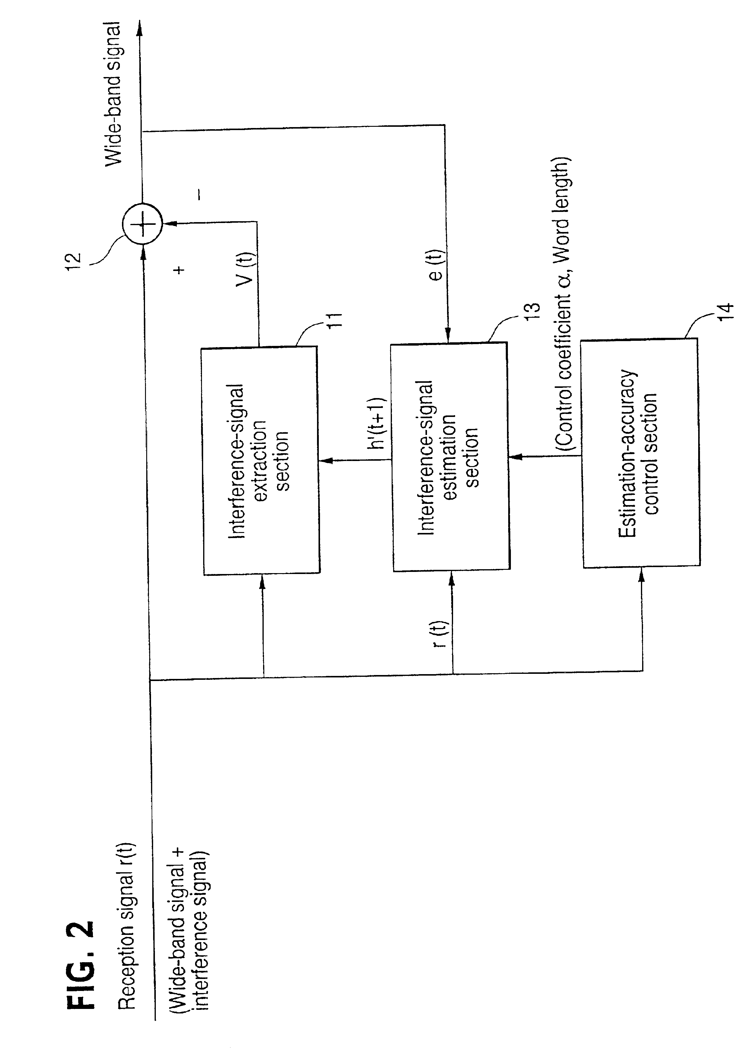
[0220]FIG. 2 shows an interference-signal removing apparatus which is provided with an interference-signal extraction section 11, a synthesizer 12, an interference-signal estimation section 13, and an estimation-accuracy control section 14. Symbol t denotes time.

[0221]The interference-signal estimation section 13 inputs a reception signal r(t) in which a wide-band desired signal and a plurality of narrow-band interference signals are synthesized and the reception signal e(t) after interference is removed, estimates interference signals included in the reception signal r(t) by using a general adaptive algorithm, and calculates the interference-signal estimation coefficient h(t+1) in accordance with the estimation result. Moreover, the interference-signal estimation section 13 of this embodiment restricts the effective word length of the calculated interference-signal...

second embodiment

[0244]Then, an interference-signal removing apparatus of second embodiment of the present invention is described below.

[0245]Because the interference-signal removing apparatus of this embodiment has the same configuration as the apparatus shown in FIG. 2, it is described by referring to FIG. 2 in the case of this embodiment for convenience' sake of description.

[0246]As shown in FIG. 2, the interference-signal removing apparatus of this embodiment is provided with an interference-signal extraction section 11, a synthesizer 12, an interference-signal estimation section 13, and an estimation-accuracy control section 14. Symbol t denotes time.

[0247]In this case, configurations and operations of the interference-signal extraction section 11 and synthesizer 12 are the same as those shown for the above first embodiment.

[0248]To calculate an interference-signal estimation coefficient h(t+1) according to an estimation result of an interference signal similarly to the case of the first embodi...

third embodiment

[0266]Then, an interference-signal removing apparatus of third embodiment of the present invention is described below.

[0267]Because the interference-signal removing apparatus of the third embodiment has the same configuration as the apparatus shown in FIG. 2, this embodiment is described by referring to FIG. 2 for convenience's sake of description.

[0268]As shown in FIG. 2, the interference-signal removing apparatus of this embodiment is provided with an interference-signal extraction section 11, a synthesizer 12, an interference-signal estimation section 13, and an estimation-accuracy control section 14. Symbol t denotes time.

[0269]In this case, configurations and operations of the interference-signal extraction section 11 and synthesizer 12 are the same as the case of the first embodiment.

[0270]To calculate an interference-signal estimation coefficient h(t+1) according to an estimation result of an interference signal similarly to the case of the first embodiment, the interference-...


PUM


Abstract

An interference-signal removing apparatus is provided for removing narrow-band interference signals from input signals including wide-band desired signals and the narrow-band interference signals, which suppresses that even desired signals are removed. The interference-signal removing apparatus includes an extraction section for extracting interference signals from input signals, a removal circuit for removing extracted interference signals from input signals, an extraction control section for controlling extraction of interference signals by the extraction section in accordance with the removal result, and an extraction-amount suppression section for suppressing the interference signal amount to be extracted in accordance with input signals.

Description

BACKGROUND OF THE INVENTION[0001]1. Field of the Invention[0002]The present invention relates to an interference signal removing apparatus for removing narrow-band interference signals from input signals including wide-band desired signals and the narrow-band interference signals, and particularly to an interference-signal removing apparatus improved in suppressing that up to a desired signal is removed.[0003]2. Description of the Prior Art[0004]For example, reception signals received by a receiver may include a signal that should be received (desired signal) and a signal interfering with the desired signal (interference signal).[0005]First, a wide-band desired signal and a narrow-band interference signal are described below by using radio LAN of IEEE 802.11 as an example.[0006]The terms “wide band” and “narrow band” are used as relative meanings. Specifically, a signal having a sufficiently-large occupying band width compared to the occupying band width of a narrow-band interferenc...

Claims


Application Information

Patent Timeline
Patent Type & Authority Patents(United States)
IPC IPC(8): H04B1/707
CPCH04B1/71
Inventor TAKADA, MASATOSHIMURAKAMI, YOICHI
Owner KOKUSA ELECTRIC CO LTD
Why Eureka
Try Eureka