Dispersion compensating fiber and dispersion compensating fiber module

a technology of fiber module and dispersion compensating fiber, which is applied in the direction of optical fibers with desired dispersion, cladded optical fibres, instruments, etc., can solve the problems of residual dispersion, difficult to manufacture the dispersion compensating fiber for nz-dsf, and difficult to completely compensate, so as to reduce the connection loss

Inactive Publication Date: 2005-08-30
THE FUJIKURA CABLE WORKS LTD
View PDF27 Cites 13 Cited by
  • Summary
  • Abstract
  • Description
  • Claims
  • Application Information

AI Technical Summary

Benefits of technology

[0022]The present invention also provides a dispersion compensating fiber module comprising any one of the above dispersion compensating fibers.
[0029]Accordingly, advantageous effects similar to that obtained by the dispersion compensating fiber of the third aspect of the present invention is obtainable.
[0030]In the above dispersion compensating fiber, the transmission loss may preferably be equal to or less than 0.7 dB/km, and the bending loss at a diameter of 20 mm at the longest wavelength in the wavelength band selected from 1.53 μm to 1.57 μm may be equal to or less than 40 dB/m.
[0031]The transmission loss may preferably be equal to or less than 0.7 dB/km, and the bending loss at a diameter of 20 mm at the longest wavelength in the wavelength band selected from 1.53 μm to 1.57 μm may be equal to or

Problems solved by technology

Because the NZ-DSF has less chromatic dispersion in the operating wavelength band than in the case of S-SMF, the ratio of dispersion slope of the dispersion compensating fiber for the NZ-DSF relative to chromatic dispersion to be compensated, i.e., relative dispersion slope (hereinafter abbreviated as RDS), is generally high, which makes it difficult to manufacture the dispersion compensating fiber for the NZ-DSF.
Therefore, it could hardly be

Method used


Image

  • Dispersion compensating fiber and dispersion compensating fiber module
  • Dispersion compensating fiber and dispersion compensating fiber module

Examples


examples a to d

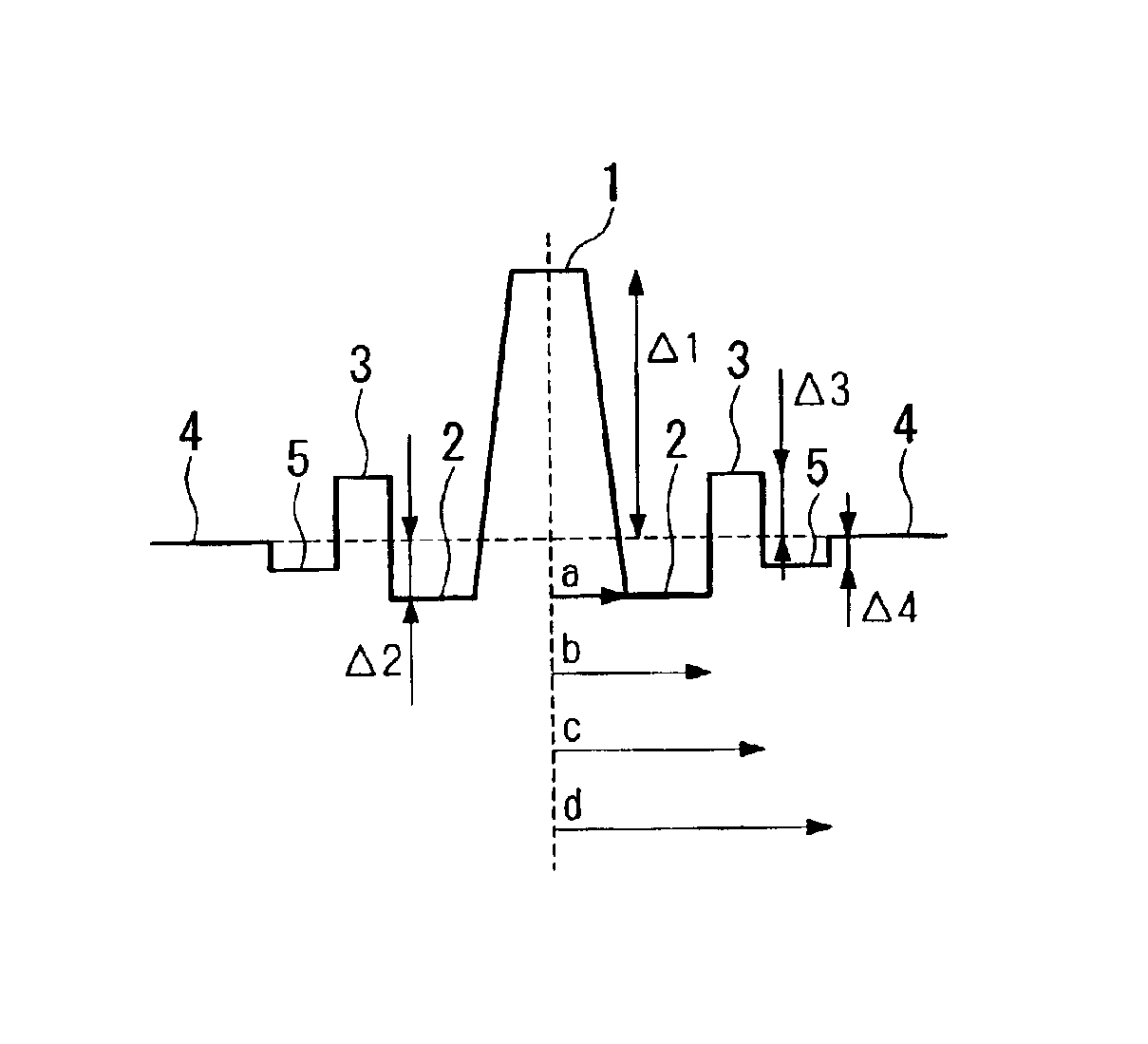
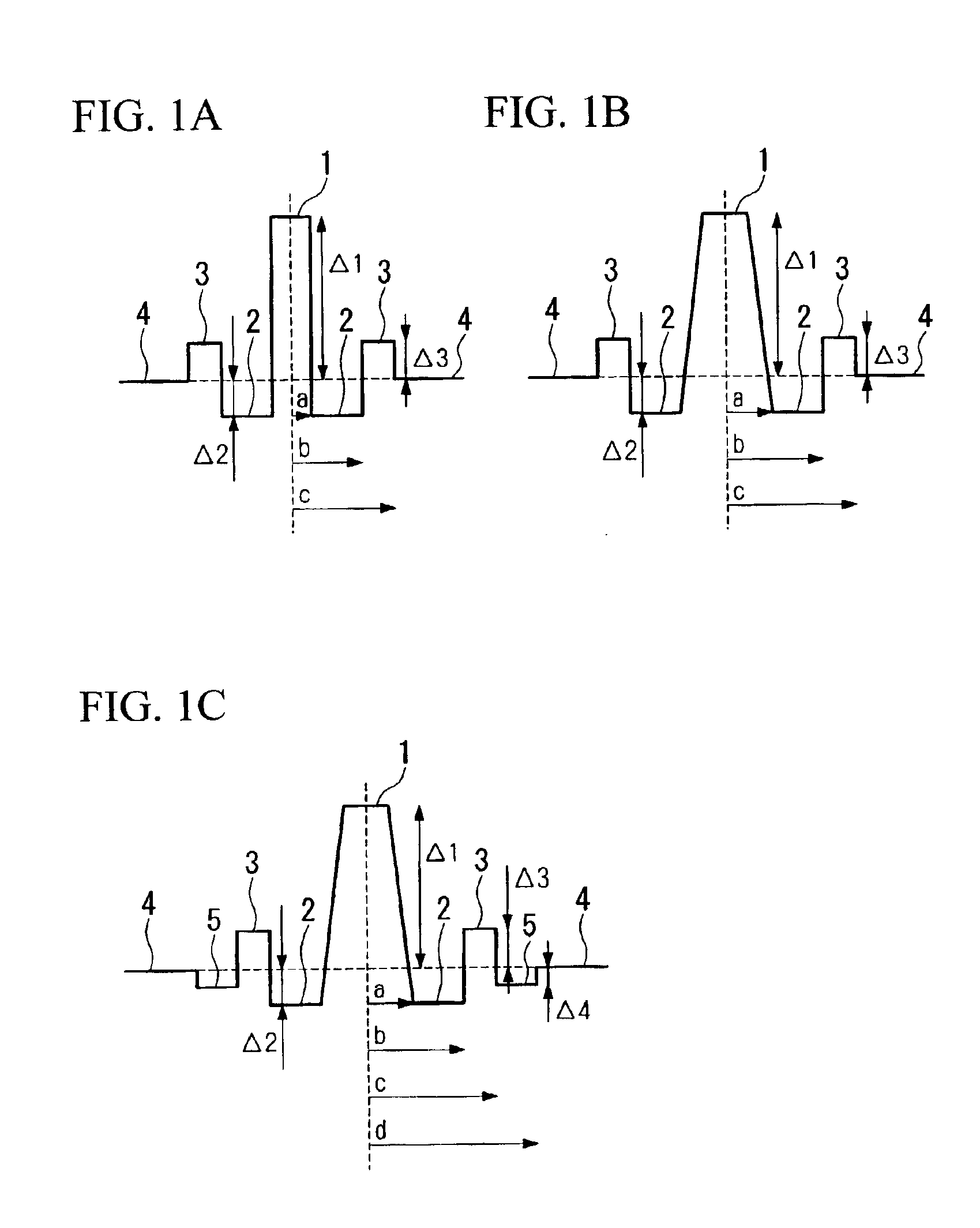
[0051]Four examples A to D of the dispersion compensating fibers in each of which the refractive index profile was set as shown in FIG. 1C, and the physical parameters Δ1, Δ2, Δ3, Δ4, b / a, c / b, and d / c were set as shown in TABLE 1, were manufactured using known manufacturing methods, such as the VAD method, the MCVD method, and the PCVD method. Please note that the dispersion compensating fiber D has the refractive index profile shown in FIG. 1B because, in this case, the layer 5 is not provided between the ring core region 3 and the cladding 4 as is shown in TABLE 1 that Δ4=0.

[0052]TABLE 1 also shows the optical properties of the dispersion compensating fibers A to D.

[0053]

TABLE 1BendingCoreWave-Trans-ChromaticDispersionlossSym-Δ1Δ2Δ3Δ4diameterlengthAeffmission lossdispersionslopeRDS(dB / m)bol(%)(%)(%)(%)b / ac / bd / c(μm)(μm)(μm2)(dB / km)(ps / nm / km)(ps / nm2 / km)(nm−1)2R = 20 mmA1.20−0.700.45−0.062.81.501.617.71.55190.35−98−0.860.008815B1.45−0.700.40−0.062.61.451.617.61.55160.30−84−0.880.010...

examples e and f

[0056]Two examples E and F of the dispersion compensating fibers in each of which the refractive index profile was set as shown in FIG. 1C, and the physical parameters Δ1, Δ2, Δ3, Δ4, b / a, c / b, and d / c were set as shown in TABLE 2, were manufactured using known manufacturing methods, such as the VAD method, the MCVD method, and the PCVD method.

[0057]TABLE 2 also shows the optical properties of the dispersion compensating fibers E and F.

[0058]

TABLE 2BendingCoreWave-Trans-ChromaticDispersionlossSym-Δ1Δ2Δ3Δ4diameterlengthAeffmission lossdispersionslopeRDS(dB / m)bol(%)(%)(%)(%)b / ac / bd / c(μm)(μm)(μm2)(dB / km)(ps / nm / km)(ps / nm2 / km)(nm−1)2R = 20 mmE1.80−0.700.40−0.102.51.461.617.31.59150.33−60−0.420.0076F1.65−0.700.45−0.072.51.461.617.31.59160.33−60−0.660.01112

[0059]The RDS in the optical fiber E is 0.007 nm−1, and the RDS in the optical fiber F is 0.011 nm−1. In these dispersion compensating fibers, the RDSs larger than that in conventional dispersion compensating fibers are obtained even tho...

examples g

to K

[0079]Five examples G to K of the dispersion compensating fibers in each of which the refractive index profile was set as shown in FIG. 1C, and the physical parameters Δ1, Δ2, Δ3, Δ4, b / a, c / b, and d / c were set as shown in TABLE 3, were manufactured using known manufacturing methods, such as the VAD method, the MCVD method, and the PCVD method. Please note that the dispersion compensating fiber L has the refractive index profile shown in FIG. 1B because, in this case, the layer 5 is not provided between the ring core region 3 and the cladding 4 as is shown in TABLE 3 that Δ4=0.

[0080]TABLE 3 also shows the optical properties of the dispersion compensating fibers G to K.

[0081]

TABLE 3Bending loss(dB / m)2R = 20 mmCoreWave-Trans-ChromaticDispersionWave-Sym-Δ1Δ2Δ3Δ4diameterlengthAeffmission lossdispersionslopeRDSlength =bol(%)(%)(%)(%)b / ac / bd / c(μm)(μm)(μm2)(dB / km)(ps / nm / km)(ps / nm2 / km)(nm−1)1.57 μmG1.45−1.500.30−0.062.61.61.67.21.55120.38−57.5−1.160.02019H1.10−1.200.20−0.062.41.81.68.61...


PUM


Abstract

A dispersion compensating fiber, which has a negative dispersion slope with a large absolute value while maintaining the absolute value of the chromatic dispersion, and which has sufficient dispersion slope compensation properties even for the non-zero dispersion shifted optical fiber requiring a large RDS for dispersion compensation. In this dispersion compensating fiber, the radius of a ring core region is set in a range from 6.7 μm to 10.7 μm, the radius ratio of a depressed core region relative to a central core region is set in a range from 2.0 to 3.0, and the radius ratio of the ring core region relative to the depressed core region is set in a range from 1.3 to 2.0, the relative refractive index difference of the central core region relative to the cladding is set in a range from +1.00% to +1.80%, the relative refractive index difference of the depressed core region relative to the cladding is set in a range from −1.20% to −1.50%, and the relative refractive index difference of the ring core region relative to the cladding is set in a range from +0.20% to +0.50%.

Description

BACKGROUND OF THE INVENTION[0001]1. Field of the Invention[0002]This invention relates to dispersion compensating fibers and to dispersion compensating fiber modules, and specifically relates to dispersion compensating fibers and to dispersion compensating fiber modules which are used to compensate dispersion in a non-zero dispersion shifted optical fiber having a chromatic dispersion of approximately a few ps / nm / km in the 1.55 μm band.[0003]2. Background Art[0004]As erbium doped optical amplifiers have become available, communication systems, specifically, using the 1.53-1.63 μm wavelength band, such as an ultra-long-haul non-regenerative repeater system, which utilize optical amplifiers, have been commercialized. On the other hand, as an increased transmission capacity is required, the wavelength division multiplexing transmission technology has been rapidly developed, and some transmission paths installed for this purpose have been commercialized. In the technical trend in the ne...

Claims


Application Information

Patent Timeline
IPC IPC(8): G02B6/036G02B6/02
CPCG02B6/02261G02B6/0228G02B6/03644G02B6/03666
Inventor AIKAWA, KAZUHIKOSHIMIZU, SHOGOSUZUKI, TAKAAKISUZUKI, RYUJINAKAYAMA, MASAKAZUHIMENO, KUNIHARU
Owner THE FUJIKURA CABLE WORKS LTD
Why Eureka
Try Eureka