Spray nozzle grid configuration for gas turbine inlet misting system

a gas turbine and inlet misting technology, which is applied in the direction of hot gas positive displacement engine plants, spraying apparatuses, machines/engines, etc., can solve the problems of less evaporation and more water carryover, the initial compressor stage is often eroded, and the peak power generation requirements of gas turbine operators are often encountered at elevated ambient temperatures

Inactive Publication Date: 2005-09-06
GENERAL ELECTRIC CO
View PDF17 Cites 20 Cited by
  • Summary
  • Abstract
  • Description
  • Claims
  • Application Information

AI Technical Summary

Benefits of technology

[0005]As a consequence of the foregoing described arrangement, the nozzles lie flush with one another in the common plane between opposite walls of the duct. The nozzles therefore do not interfere with one another and the nozzle plumes are not interfered with by other nozzles or manifolds. A uniformity of water spray is thus achieved without an increase in water droplet carryover to the compressor. The nozzles and manifolds are arranged such that a turndown of one of the manifolds in each group of three manifolds still provides for substantial uniformity of the spray pattern in the duct. Additionally, the location of the nozzles in the duct preferably corresponds to the location of the most uniform air flow within the duct. It has been found that by extending the duct between the inlet duct silencer and the mister and before the downturn or elbow to the compressor inlet, a more uniform flow of humidified air is provided.

Problems solved by technology

However, gas turbine operators frequently encounter peak power generating requirements at elevated ambient temperatures, e.g., due to high air conditioning loads in major cities.
However, as the water supply is turned down, the spray pattern in the inlet duct becomes much less uniform, resulting in less evaporation and more water carryover.
Water carryover, e.g., large droplets of water, entering the compressor have the potential to erode the initial compressor stage.
Additionally, the air flow is disrupted by the nozzles and ancillary piping in the inlet duct, resulting in reduced evaporation.
These disruptions oftentimes disadvantageously form vortices in the flow downstream of the manifold tubes.

Method used


Image

  • Spray nozzle grid configuration for gas turbine inlet misting system
  • Spray nozzle grid configuration for gas turbine inlet misting system
  • Spray nozzle grid configuration for gas turbine inlet misting system

Examples


Embodiment Construction

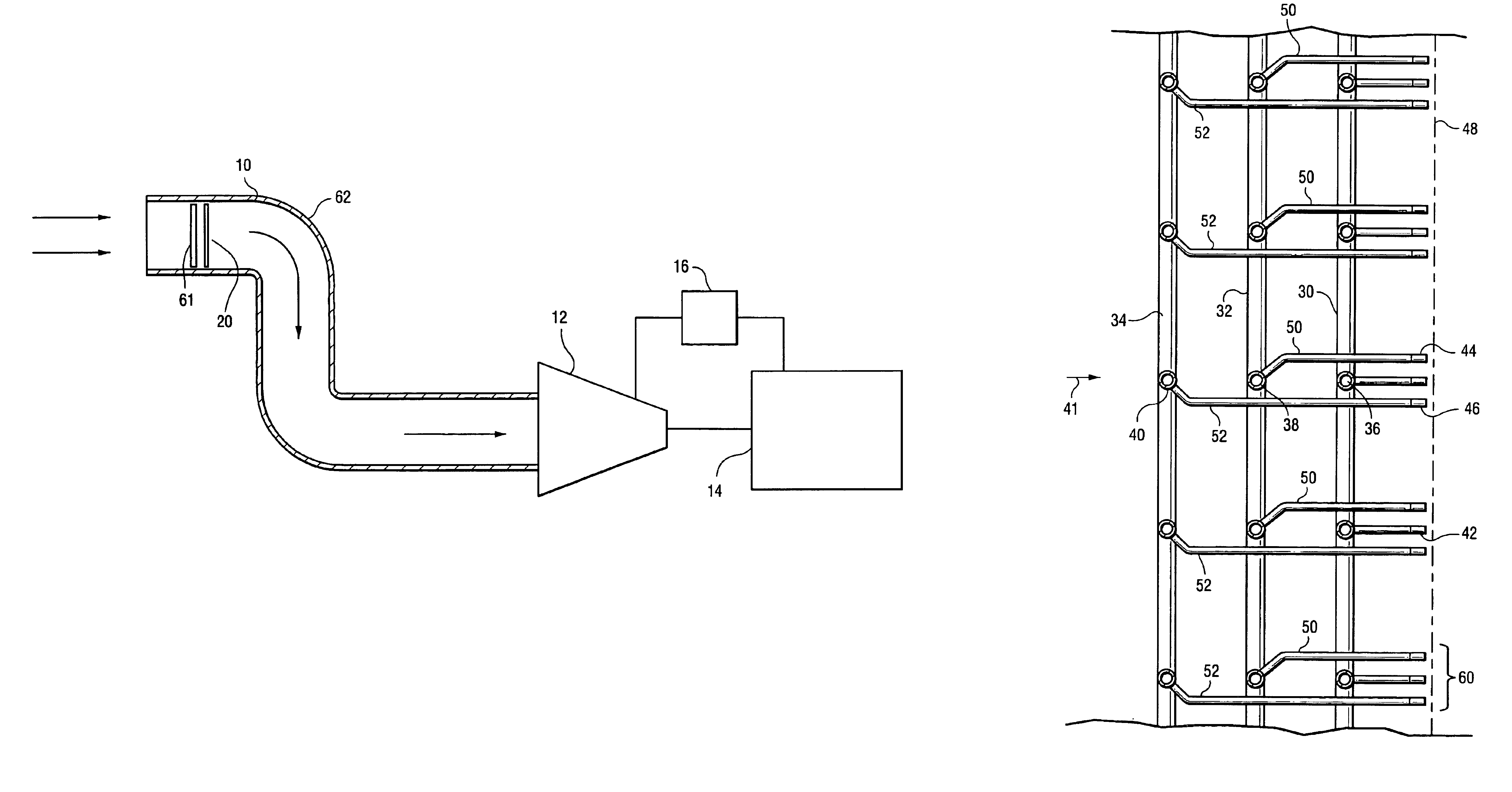
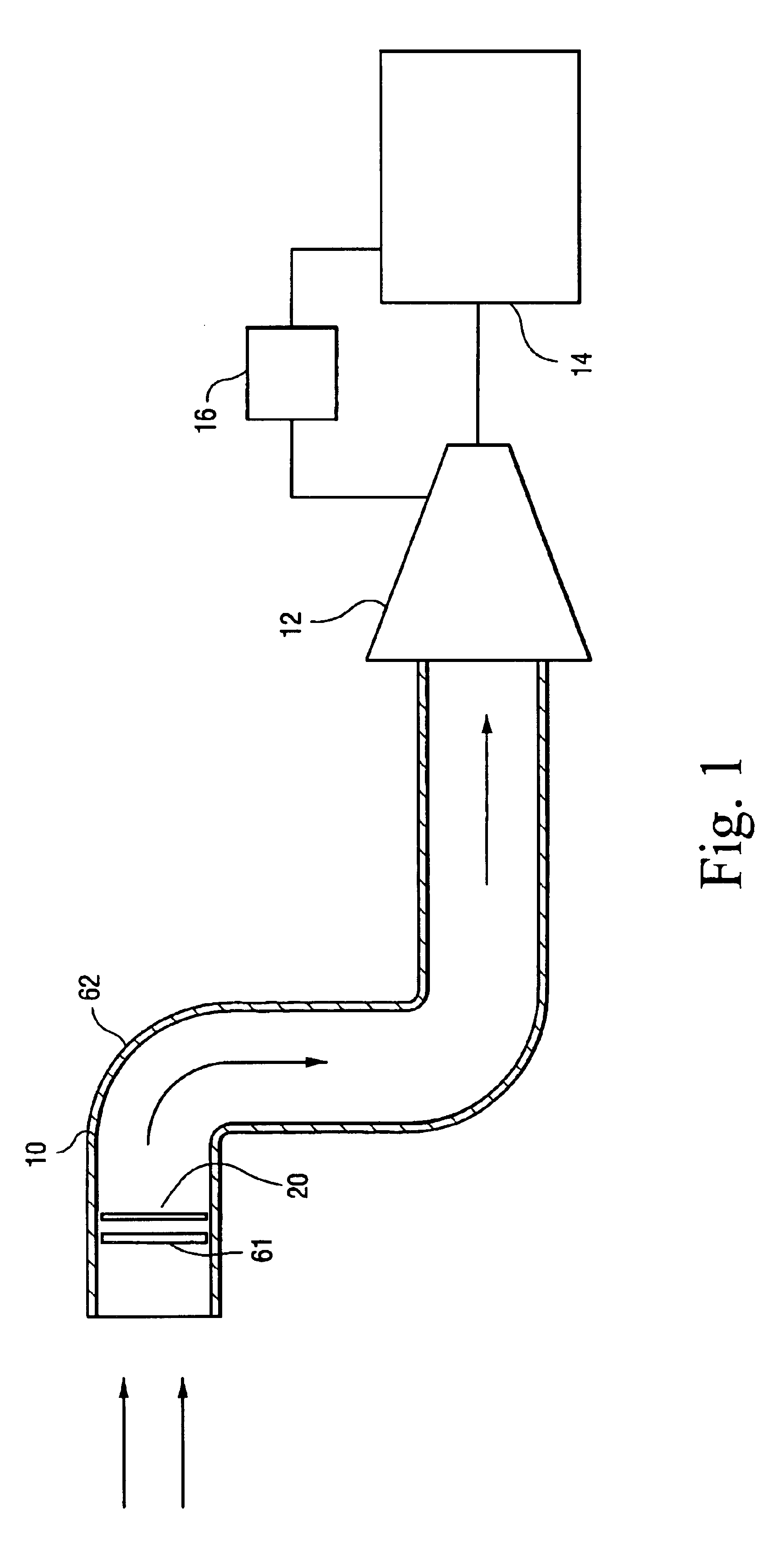
[0012]Referring to FIG. 1, there is illustrated an inlet duct 10 for supplying ambient air to the inlet of a compressor 12 driven by a turbine 14. Combustors 16 are illustrated utilizing a portion of the compressed air for combustion and flowing the products of combustion into the turbine 14 to drive the latter and the compressor. As noted previously, gas turbine output decreases in proportion to increase in the ambient air temperature and, accordingly, a mister apparatus, generally designated 20, is disposed in the inlet duct 10 to provide a direct water spray evaporative cooling system, thereby to increase gas turbine output.

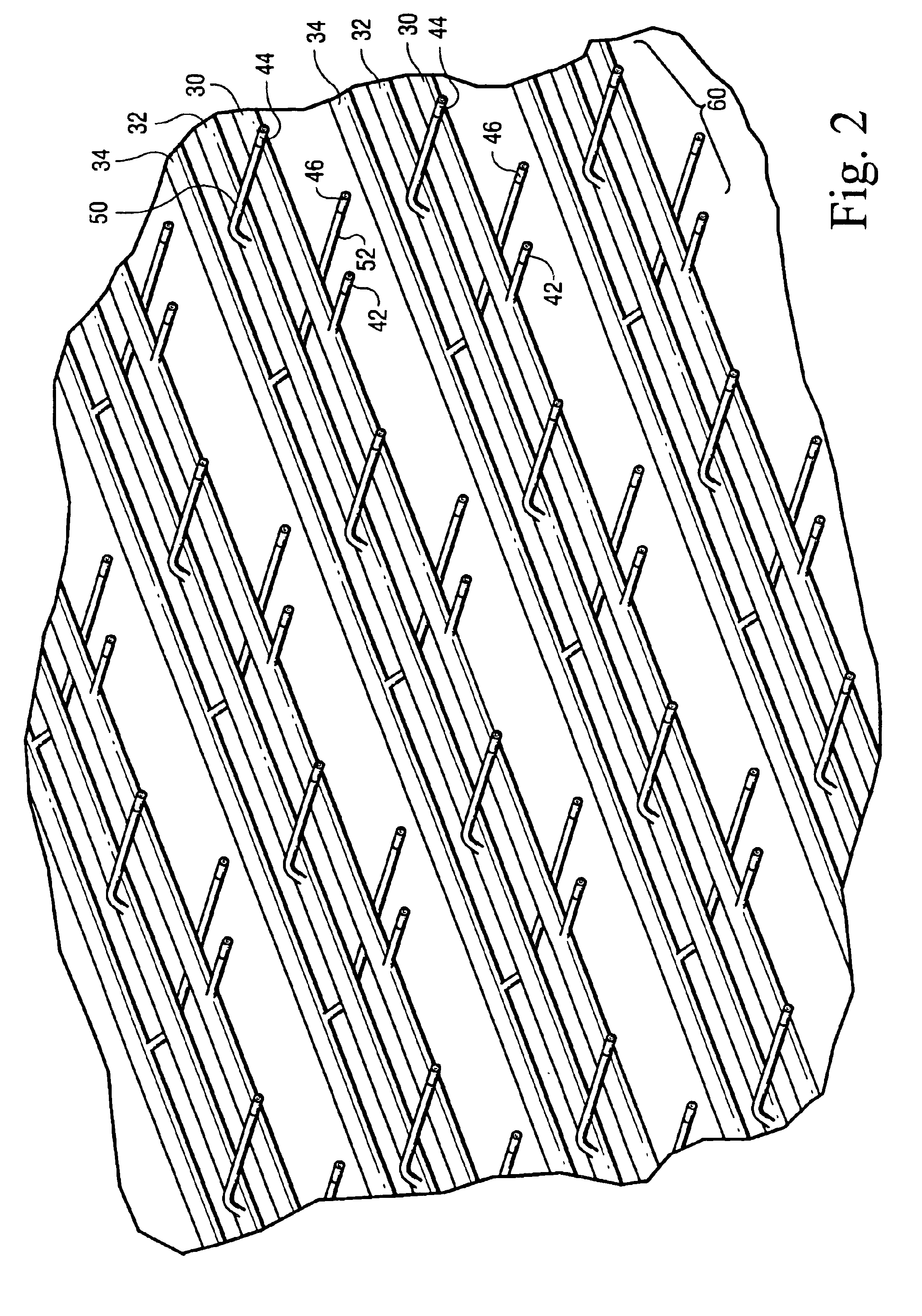
[0013]Referring now to FIGS. 2 and 3, the mister apparatus includes an array of nozzles for spraying water in the duct 10 for evaporation and humidification of the air inlet to the compressor 12. As illustrated in FIG. 3, a series of headers 30, 32 and 34 along one or both sides of the duct supply water to a series of manifolds 36, 38 and 40, extending from th...


PUM


Abstract

The mister includes a plurality of manifolds extending between opposite sides of a duct. Each manifold carries a plurality of nozzles at laterally spaced positions along the length of the manifold. The manifolds are spaced one behind the other in the direction of air flow in the duct and the pipes connecting the nozzles of the intermediate and upstream manifolds bypass the downstream manifolds to provide the nozzles in a common plane perpendicular to the direction of air flow in the duct. This arrangement affords a uniformity of spray and, hence, a uniformity of humidified air to the inlet of the compressor.

Description

BACKGROUND OF THE INVENTION[0001]The present invention relates to a spray nozzle grid configuration forming part of a misting system for humidifying air supplied to the inlet of a compressor for a turbine and particularly relates to a grid system for reducing obstruction to the flow of air in the inlet duct to the compressor while simultaneously affording substantially uniform distribution of the humidified air across the duct.[0002]It is well known in gas turbine operation, that turbine output decreases in proportion to increases in ambient air temperature. However, gas turbine operators frequently encounter peak power generating requirements at elevated ambient temperatures, e.g., due to high air conditioning loads in major cities. It is economical and advantageous to generate additional power through auxiliary systems during those peak power demand periods. One auxiliary system for increasing power input is an inlet misting or fogging system which provides a direct spray of water...

Claims


Application Information

Patent Timeline
Patent Type & Authority Patents(United States)
IPC IPC(8): F02C3/20F02C3/30
CPCF02C3/305
Inventor CARBERG, WILLIAM GEORGETREWIN, RICHARD ROBERT
Owner GENERAL ELECTRIC CO
Why Eureka
Try Eureka