
Thrust vectoring and variable exhaust area for jet engine nozzle

a jet engine and exhaust area technology, applied in the field of exhaust nozzles, can solve the problems of reducing aircraft efficiency, affecting the overall dispatch reliability and operational cost of business or commercial aircraft, and atypical technology, so as to reduce the required landing speed of aircraft, improve the longitudinal stability of aircraft, and improve the effect of aircraft longitudinal stability

Inactive Publication Date: 2005-09-06
PROPULSION VECTORING
View PDF88 Cites 61 Cited by
  • Summary
  • Abstract
  • Description
  • Claims
  • Application Information

AI Technical Summary

Benefits of technology

[0023]It is still another object of the present invention to provide a jet engine nozzle with a large angle of thrust vectoring and large variable exhaust area capabilities.
[0027]It is still yet another object of the present invention to provide a jet engine nozzle that improves the longitudinal stability of an aircraft.
[0028]It is still yet another object of the present invention to provide a jet engine nozzle that reduces the required landing speed of an aircraft.

Problems solved by technology

Some of the reasons for this are that the technology is typically very complex and involves many moving parts, which is detrimental to the overall dispatch reliability and operational cost of a business or commercial aircraft.
These opposing forces help maintain stability but create drag, which in turn reduces aircraft efficiency.
This can greatly reduce the effectiveness of the tail in countering the nose up pitching moment.
When the nose up pitching moment created by the wing during stall is greater than the nose down pitching moment created by the horizontal tail, recovery from the stall may be impossible.
However, these reversers that are used at landing for about 30 seconds can produce catastrophic events if an inadvertent deployment occurs during flight.
Furthermore, if power for the thrust vectoring system is different from the flight control system i.e., electric vs. hydraulic, then an additional level of redundancy is created, which further increases the overall safety of the aircraft.

Method used


Image

  • Thrust vectoring and variable exhaust area for jet engine nozzle
  • Thrust vectoring and variable exhaust area for jet engine nozzle
  • Thrust vectoring and variable exhaust area for jet engine nozzle

Examples


Embodiment Construction

[0088]In the following detailed description of the preferred embodiments, reference is made to the accompanying drawings which form a part hereof, and in which is shown by way of illustration specific preferred embodiments in which the invention may be practiced. These embodiments are described in sufficient detail to enable those skilled in the art to practice the invention, and it is understood that other embodiments may be utilized and that logical structural, mechanical, electrical, and material changes may be made without departing from the spirit or scope of the invention. To avoid detail not necessary to enable those skilled in the art to practice the invention, the description may omit certain information known to those skilled in the art. The following detailed description is, therefore, not to be taken in a limiting sense, and the scope of the present invention is defined only by the appended claims.

[0089]In this continuation-in-part of U.S. application Ser. No. 09 / 842,178...


PUM


Abstract

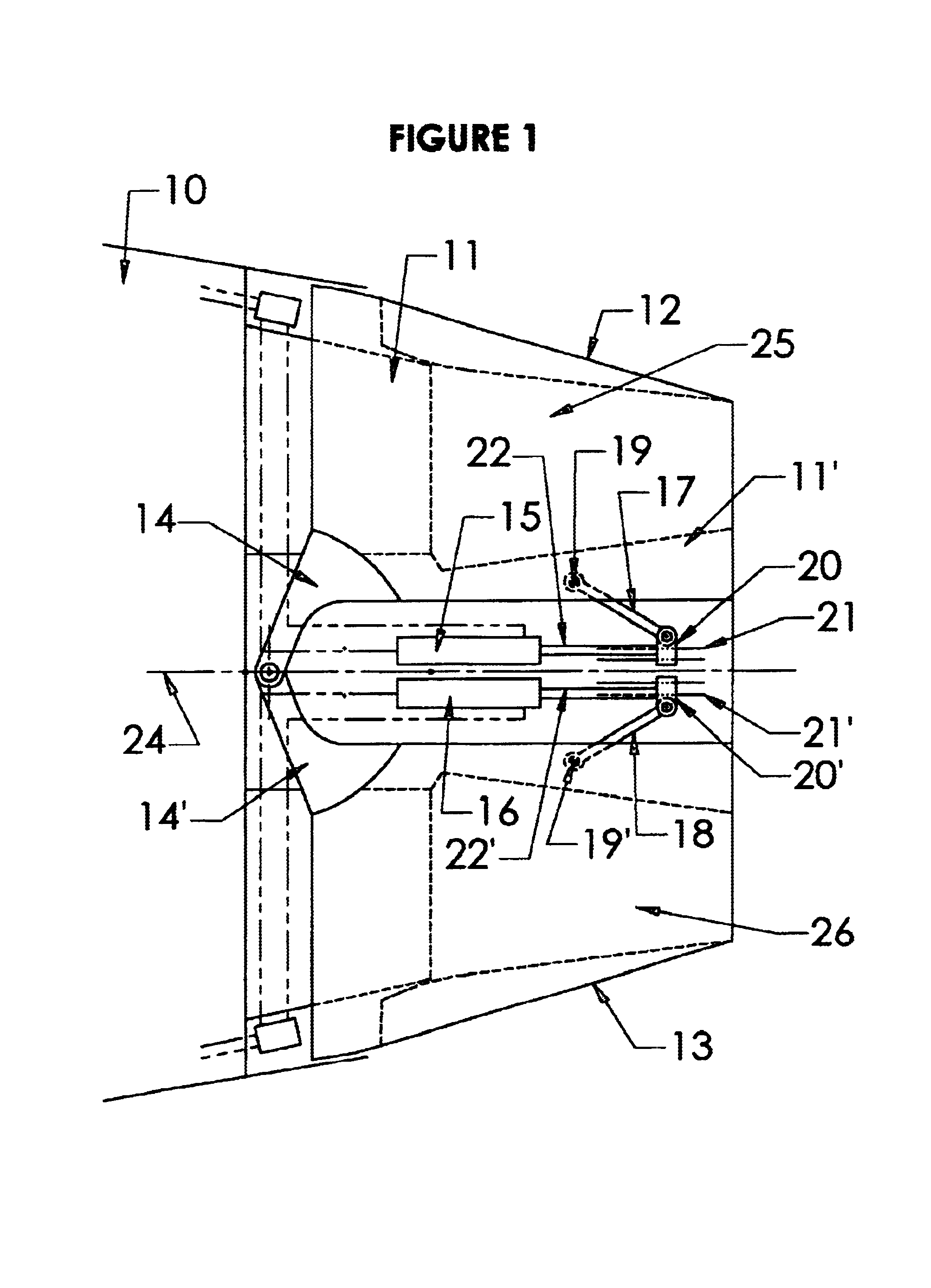
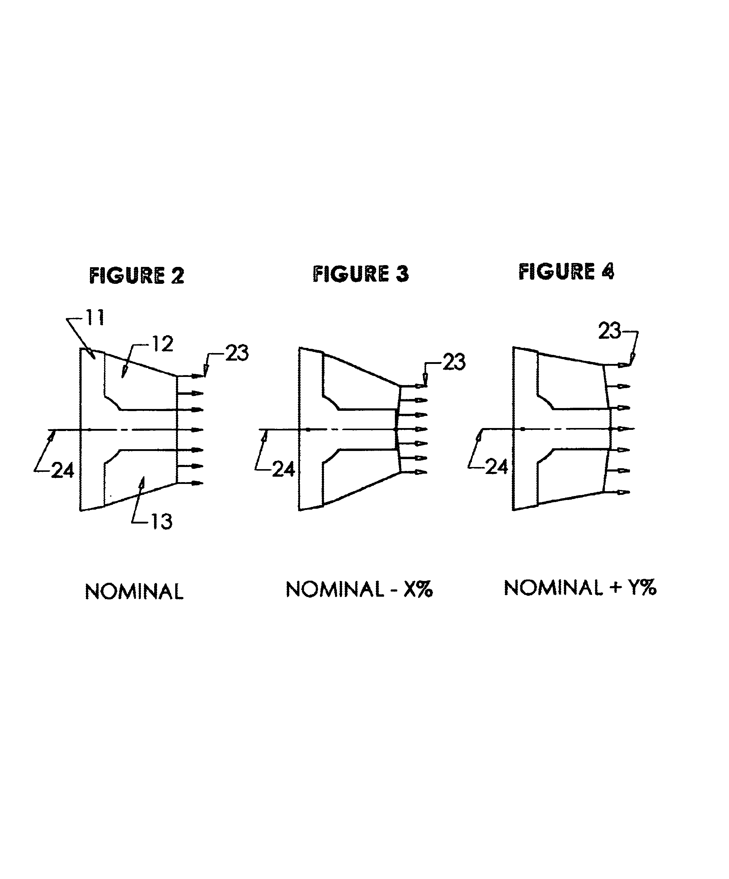
A jet engine nozzle having a pair of pivoting extension arms and a pair of pivoting shells connected to a jet pipe is provided. The first extension arm is pivotally connected to the jet pipe at a first location, while the second extension arm is pivotally connected to the jet pipe at a second location. Each shell is pivotally connected at both the first and second locations. An axis of rotation associated with the first location is coaxial to an axis of rotation associated with the second location. Independent actuation means are provided to rotate the extension arms and the shells, thereby enabling adjustment of the thrust-vector angle or the exhaust area of the nozzle.

Description

CROSS-REFERENCES TO RELATED APPLICATIONS[0001]This application is a continuation-in-part of U.S. application Ser. No. 09 / 842,178, filed Apr. 26, 2001, which is hereby incorporated by reference and now U.S Pat. No. 6,546,716. The application also claims the benefit of U.S. Provisional Application No. 60 / 410,833, filed Sep. 16, 2002, which is hereby incorporated by reference.BACKGROUND OF THE INVENTION[0002]1. Field of the Invention[0003]The present invention relates generally to exhaust nozzles for jet engines, and in particular to a jet-engine-exhaust nozzle that may be used on fixed or rotary wing aircraft, rockets, or missiles for optimizing take-off, climb and cruise performance, as well as for increasing flight safety and reducing speed at landing.[0004]2. Description of Related Art[0005]Thrust vectoring technology has been successfully demonstrated on tactical military aircraft to provide maneuvering advantages in very low speed, as well as very high angle-of-attack flight regi...

Claims


Application Information

Patent Timeline
Patent Type & Authority Patents(United States)
IPC IPC(8): B64C15/00B64C15/02F02K1/11F02K1/54F02K1/12F02K1/15F02K1/70F02K1/60F02K1/00F02K1/04F02K1/76F02K1/80
CPCB64C15/02F02K1/002F02K1/006F02K1/04F02K1/11F02K1/1261F02K1/15F02K1/54F02K1/60F02K1/70F02K1/76F02K1/805Y02T50/672F05D2240/55Y02T50/60
Inventor LAIR, JEAN-PIERRE
Owner PROPULSION VECTORING
Learn More