Striking tool

a technology of cylinder and cylinder head, which is applied in the field of cylinder tools, can solve the problems of poor integrating performance and cylinder b>2/b> inclination, and achieve the effect of excellent integrating performance and promotion of cylinder tools

Active Publication Date: 2005-09-06
KOKI HLDG CO LTD
View PDF12 Cites 103 Cited by
  • Summary
  • Abstract
  • Description
  • Claims
  • Application Information

AI Technical Summary

Benefits of technology

[0012]It is an object of the invention to provide a striking tool eliminating the above-described drawbacks of the related art and having excellent integrating performance.
[0013]Further, it is an object of the invention to provide a striking tool having excellent integrating performance even in a constitution of having an idle striking preventing mechanism.
[0015]By thus configuration, the striking tool can be promoted and the striking piece having excellent integrating performance can be provided.

Problems solved by technology

Particularly, when there is configured by an idle striking preventing mechanism for preventing continuous reciprocating movement of the striker 8 at no load time, since the slide sleeve 15, the spring 14 and the like are provided on the outer periphery of the cylinder 2, there is needed a space between the outer periphery of the cylinder 2 and the cylinder case 3 at a vicinity of substantially a center of the cylinder 2, in integrating the cylinder 2, the cylinder 2 is liable to incline and the integrating performance is poor.

Method used


Image

  • Striking tool
  • Striking tool
  • Striking tool

Examples


Embodiment Construction

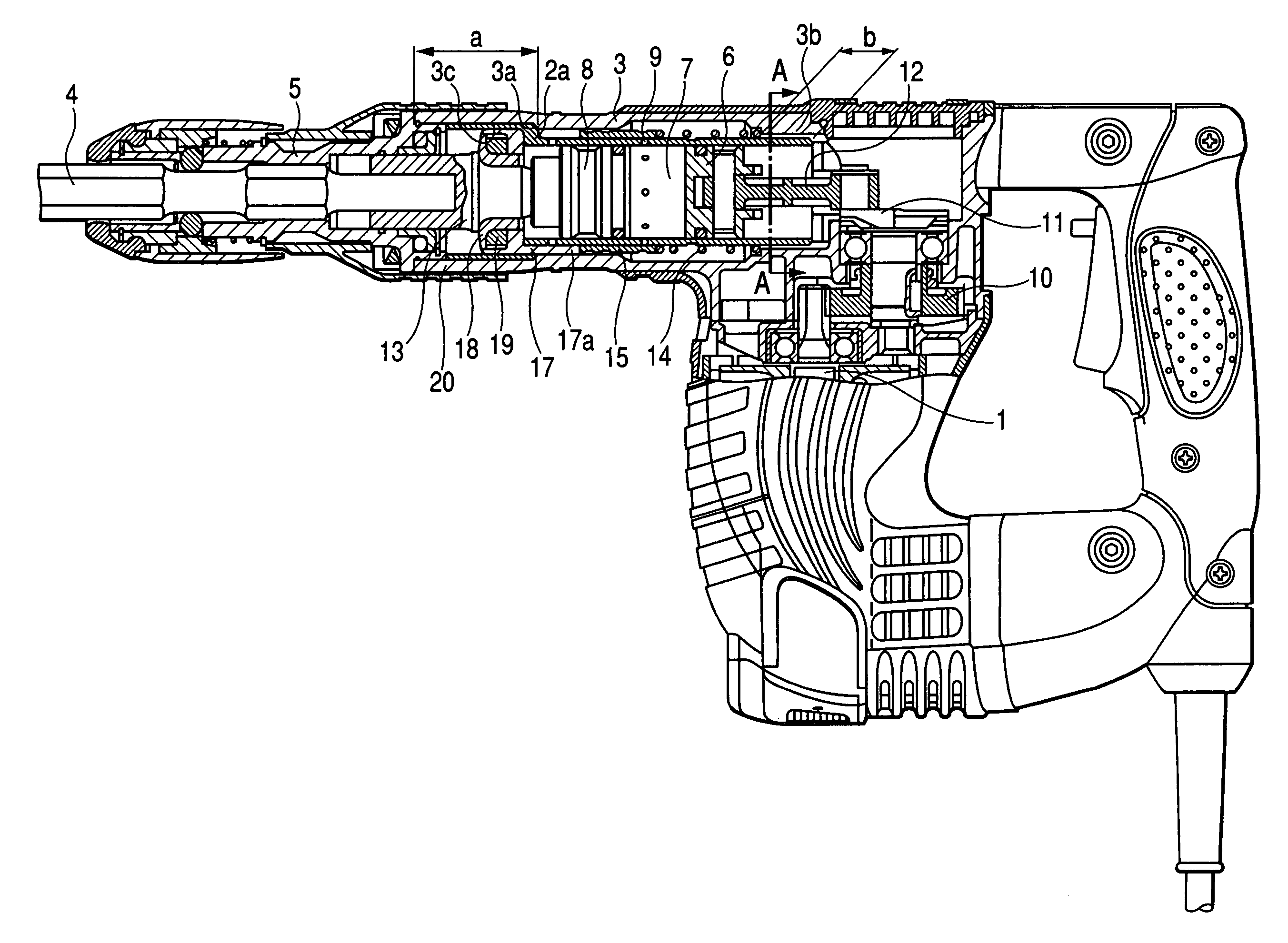
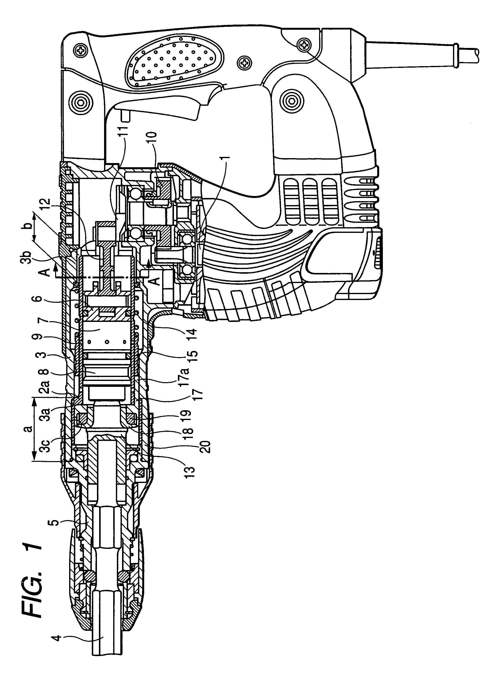
[0025]An embodiment of a striking tool according to the invention will be explained in reference to FIG. 1 through FIG. 5 as follows.

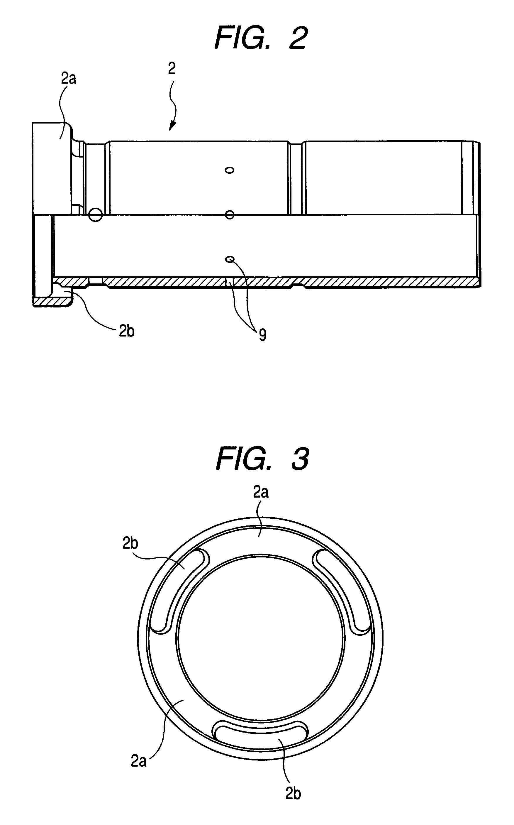
[0026]As shown by the drawings, a striking tool according to one embodiment of the invention is configured by the motor 1, the cylinder 2, the cylinder case 3 covering the outer periphery of the cylinder 2, the tool holding portion 5 capable of holding the front end tool 4, the piston 6 capable of reciprocating at inside of the cylinder 2, the striker 8 exerted with the reciprocating force of the cylinder 6 via the air chamber 7 and reciprocating at inside of the cylinder 2, the breathing hole 9 provided at the outer periphery of the cylinder 2 and communicatable with the air chamber 7, the crankshaft 11 which is a movement converting member exerted with the rotational force of the motor 1 via the reduction gear 10 and converting the rotational force into the reciprocating force to transmit to the piston 6 via the connecting rod 12, the middle piece 13...


PUM

PropertyMeasurementUnit
reciprocating forceaaaaaaaaaa
rotational forceaaaaaaaaaa
striking forceaaaaaaaaaa

Abstract

A projected portion provided at a cylinder and projected in a radius direction is formed at an end face thereof on a side of a tool holding portion, and a holding portion on one side of holding portions for holding an outer periphery of the cylinder by at least two portions remote from each other in an axial direction to position in the radius direction of the cylinder is configured by a guide face having an inner diameter of a dimension substantially the same as an outer diameter of the projected portion and extended over to a contact face brought into contact with the projected portion from an end face of a cylinder case on a side of the tool holding portion.

Description

BACKGROUND OF THE INVENTION[0001]1. Field of the Invention[0002]The present invention relates to a striking tool such as a hammer, a hammer drill which is configured to position a cylinder at inside of a cylinder case.[0003]2. Description of the Related Art[0004]A striking tool of a related art will be explained in reference to FIG. 6 through FIG. 8.[0005]As shown by the drawings, a striking tool of a related art is configured by a structure including a motor 1, a cylinder 2, a cylinder case 3 covering an outer periphery of the cylinder 2, a tool holding portion 5 capable of holding a front end tool 4, a piston 6 capable of reciprocating at inside of the cylinder 2, a striker 8 reciprocating at inside of the cylinder 2 by being exerted with a reciprocating force of the piston 6 via an air chamber 7, a breathing hole 9 provided at the outer periphery of the cylinder 2 and communicatable with the air chamber 7, a crankshaft 11 exerted with a rotational force of the motor 1 via a reduc...

Claims


Application Information

Patent Timeline
Patent Type & Authority Patents(United States)
IPC IPC(8): B25D11/00B25D17/00B25D17/06B25D16/00B25D9/00B25D11/06B25D11/12
CPCB25D11/005B25D17/06B25D11/125B25D2211/003
Inventor KIKUCHI, ATSUYUKI
Owner KOKI HLDG CO LTD
Why Eureka
Try Eureka