Tray carrier with ultraphobic surfaces

a technology of ultra-lyophobic surfaces and tray carriers, which is applied in the field of tray carriers, can solve the problems of uneconomical cleaning of tray carriers, often extremely sensitive to contamination, and accumulate some amount of contamination, so as to promote more effective cleaning and drying of the carrier, and less time and energy is expended in drying the surface. , the effect of promoting the effect of effective cleaning and drying

Inactive Publication Date: 2005-09-06
ENTEGRIS INC
View PDF35 Cites 33 Cited by
  • Summary
  • Abstract
  • Description
  • Claims
  • Application Information

AI Technical Summary

Benefits of technology

[0010]The present invention includes a tray carrier with ultraphobic surfaces for promoting more effective cleaning and drying of the carrier. In the invention, entire surfaces or portions of surfaces of a carrier are made ultraphobic. The ultraphobic surfaces of the carrier cause liquids that may come in contact with the surface, such as may be used in cleaning, to quickly and easily “roll off” without leaving a liquid film or substantial number of liquid droplets. As a result, less time and energy is expended in drying the surfaces, and redeposited residue is minimized, thereby improving overall process quality. In addition, the ultraphobic surfaces may be resistant to initial deposition of contaminants, where the contaminants may be in liquid or vapor form.

Problems solved by technology

Electronic device fabrication processes, particularly where semiconductors are involved, are often extremely sensitive to contamination.
As a tray carrier is used through a fabrication process, it will generally accumulate some amount of contamination.
In the past, cleaning of tray carriers has often been considered uneconomical in view of the relatively low cost of new tray carriers and the relatively high cost and difficulty of cleaning and reusing contaminated tray carriers.
Previously, cleaning of tray carriers has been made more difficult and expensive due to the need to dry the tray after cleaning with water or other solvents.
The tray carrier may have intricate arrangements of surfaces that are difficult to dry.
Any contaminants suspended in the residual cleaning fluid may be redeposited on the surface as the fluid dries, leading to contaminant carryover when the carrier is reused.
Consequently, process efficiency and effectiveness is diminished overall.
Reuse of tray carriers is discouraged, leading to environmentally undesirable proliferation of solid waste.

Method used


Image

  • Tray carrier with ultraphobic surfaces
  • Tray carrier with ultraphobic surfaces
  • Tray carrier with ultraphobic surfaces

Examples


Embodiment Construction

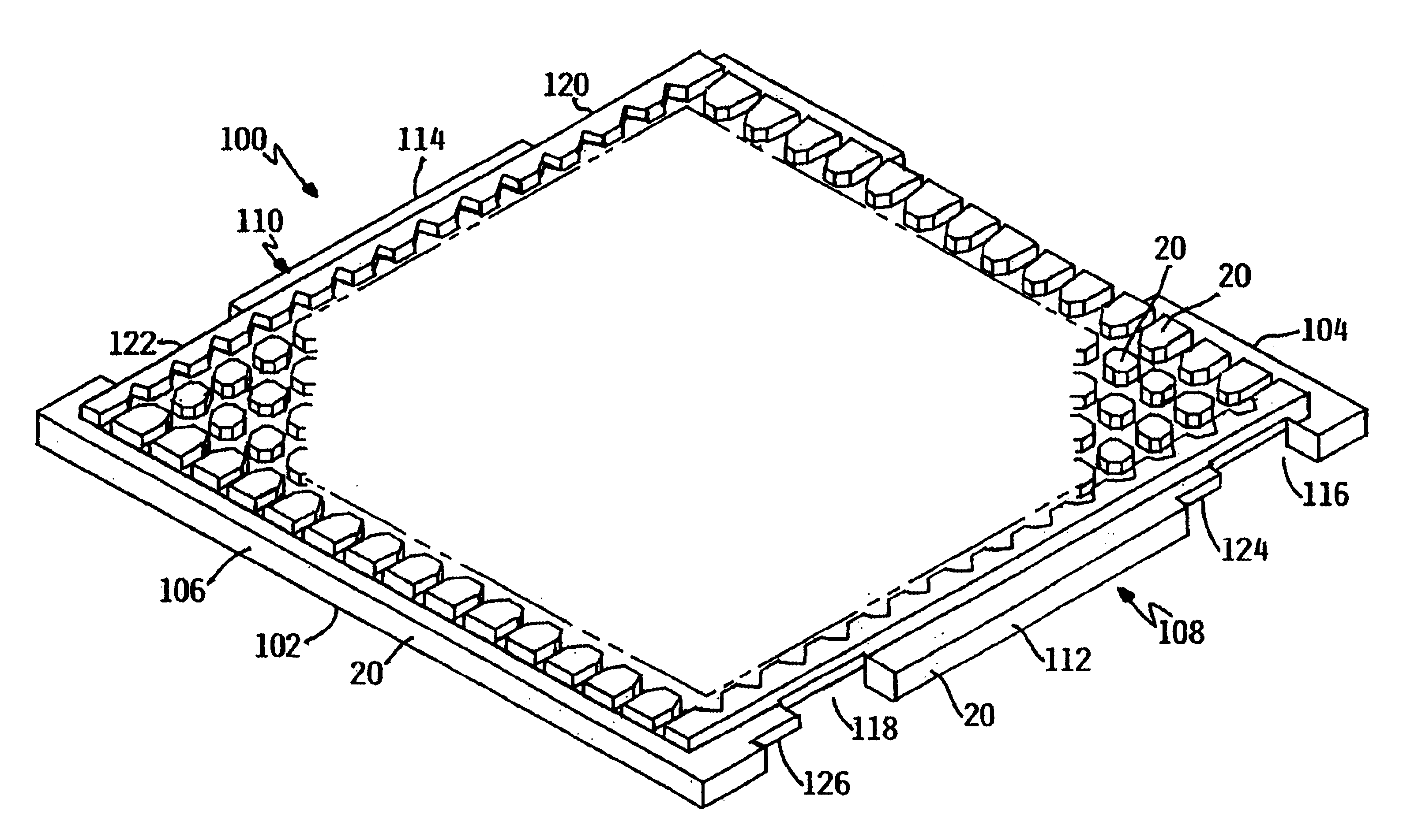
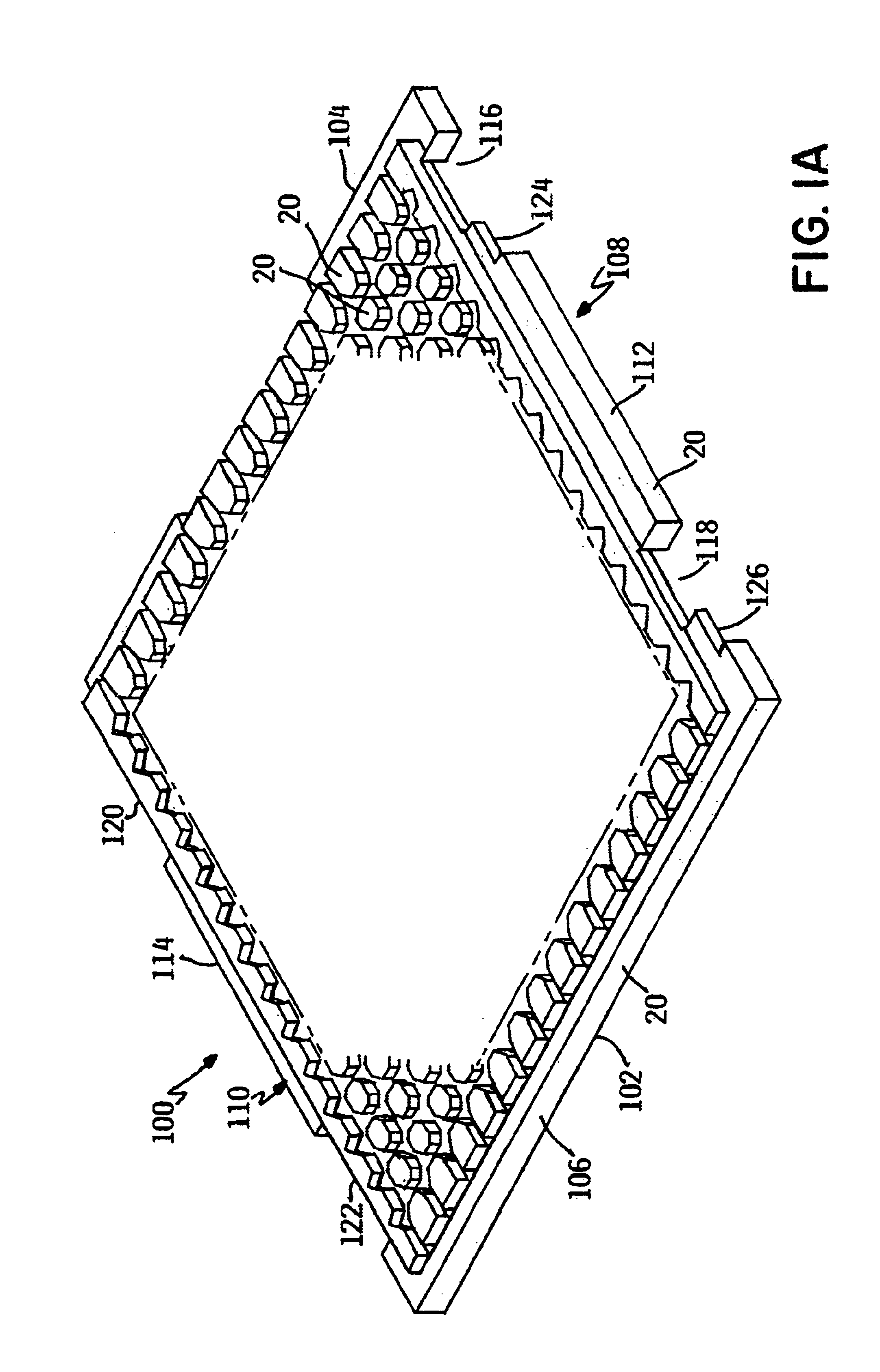
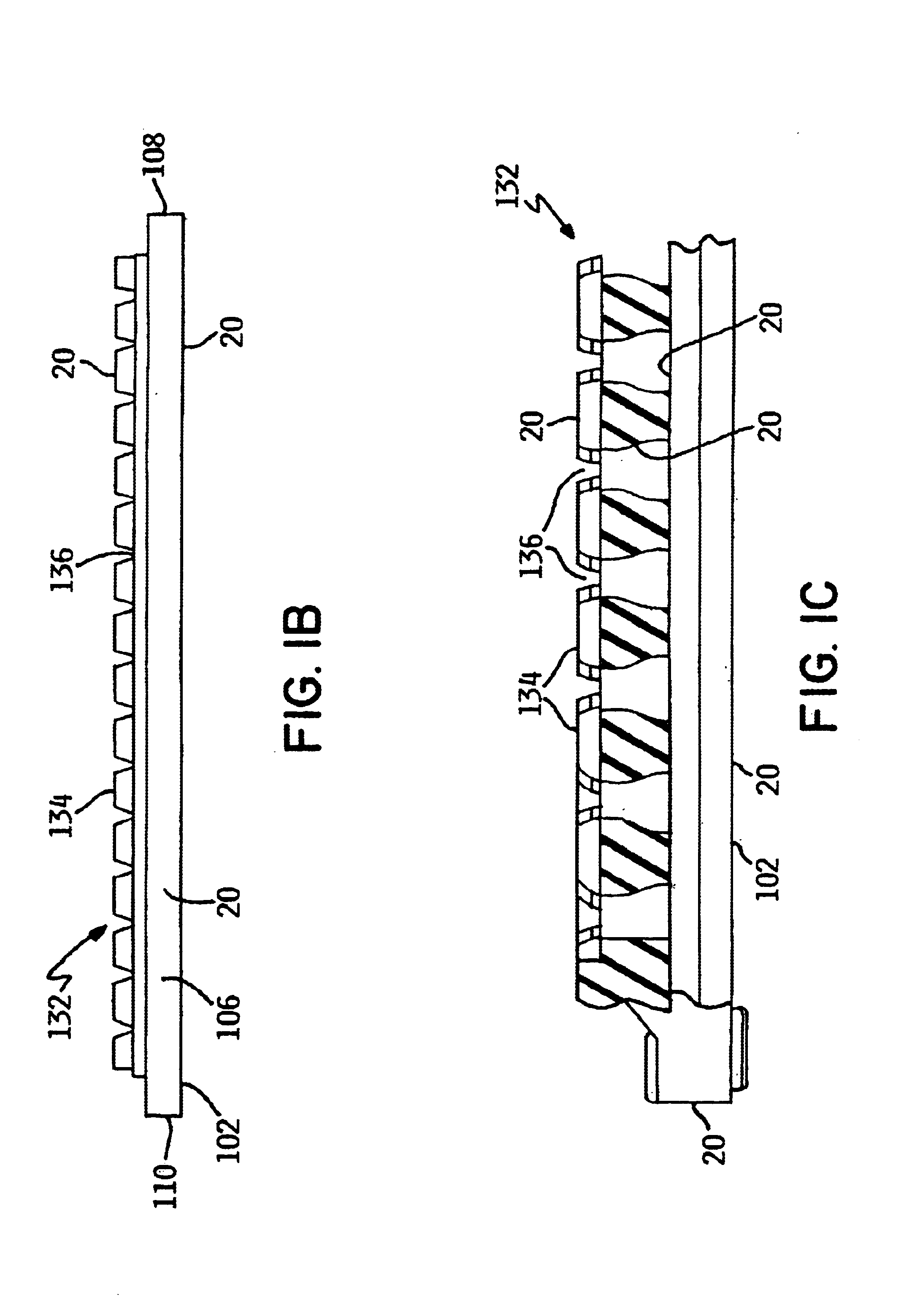
[0035]Referring to FIGS. 1a, 1b and 1c, an example of a tray carrier for processing and transporting a plurality of electronic devices such as semi-conductor chips is shown and generally designated by the numeral 100. The tray 100 comprises a first peripheral frame 102 having a first end 104, a second end 106, and sides 108, 110. Sides 108, 110 include rails 112, 114 and notches 116, 118, 120, and 122, located at the ends of rails 112 and 114, respectively. Tabs 124, 126, 128, and 130 project into notches 116, 118, 120, and 122 for engagement with flanges (not depicted). Note that the tabs 124, 126, 128, and 130 project in the same direction relative to the tray 100. Together, first end 104, second end 106 and the rails 112, 114 extend substantially around the perimeter of a chip support surface 132. The chip support surface 132 is of a conventional design and is depicted as a matrix of lands 134 which define pockets or cells 136 which hold individual chips. Referring to FIG. 1b, th...


PUM


Abstract

A tray carrier with ultraphobic surfaces for promoting more effective cleaning and drying of the tray carrier. In the invention, entire surfaces or portions of surfaces of a tray carrier are made ultraphobic. The ultraphobic surfaces of the tray carrier cause liquids that may come in contact with the surface, such as may be used in cleaning, to quickly and easily “roll off” without leaving a liquid film or substantial quantity of liquid droplets. As a result, less time and energy is expended in drying the surfaces, and redeposited residue is minimized, thereby improving overall process quality and facilitating economical reuse of the tray carrier. In addition, the ultraphobic surfaces may be resistant to initial deposition of contaminants, where the contaminants may be in liquid or vapor form.

Description

RELATED APPLICATIONS[0001]This application claims the benefit of U.S. Provisional Patent Application Ser. No. 60 / 462,963, entitled “Ultraphobic Surface for High Pressure Liquids”, filed Apr. 15, 2003, hereby fully incorporated herein by reference.FIELD OF THE INVENTION[0002]The present invention relates generally to tray carriers for delicate electronic components, and more particularly to a tray carrier having ultrahydrophobic or ultralyophobic surfaces formed thereon.BACKGROUND OF THE INVENTION[0003]Trays are used in the micro-electronic industry for storing, transporting, fabricating, and generally holding small components such as, but not limited to, semi-conductor chips, ferrite heads, magnetic resonant read heads, thin film heads, bare dies, bump dies, substrates, optical devices, laser diodes, preforms, and miscellaneous mechanical articles such as springs and lenses.[0004]Semi-conductor chips (chips) are illustrative of the issues associated with handling the above-defined c...

Claims


Application Information

Patent Timeline
Patent Type & Authority Patents(United States)
IPC IPC(8): B01L9/00B01L3/00B08B17/00B08B17/06F15D1/06F15D1/00B01L11/00H01L21/67H01L21/673B01L99/00
CPCB01L3/502707B01L9/527B08B17/06B08B17/065F15D1/065B01L3/5027B01L9/52B01L2300/166B65G2201/0258B01L13/02B65D85/00B65D85/48B82Y30/00
Inventor EXTRAND, CHARLES W.
Owner ENTEGRIS INC
Why Eureka
Try Eureka