Apparatus and system for synchronized application of one or more materials to a surface from a vehicle and control of a vehicle mounted variable position snow removal device

Inactive Publication Date: 2005-09-06
WEATHER INSIGHTS
View PDF85 Cites 73 Cited by
  • Summary
  • Abstract
  • Description
  • Claims
  • Application Information

AI Technical Summary

Benefits of technology

[0018]The third embodiment of the present invention incorporates an on board system for sensing and analyzing actual road surface conditions at the vehicle location and utilizes an on board computer and database to selectively manually or automatically control the application of spreader materials and/or certain operations of a vehicle preferably equipped with a snow plow or blower. The third embodiment includes Global Position

Problems solved by technology

The problem with the conventional material spreading systems resides in the difficulty in accurately adjusting the spread-width of each material, in addition to the time and attention it takes for the operator to modify the spread-width while driving the vehicle.
A similar problem exists for operators of surface conditioning vehicles which include snow plows and snow blowers, especially in resident

Method used


Image

  • Apparatus and system for synchronized application of one or more materials to a surface from a vehicle and control of a vehicle mounted variable position snow removal device
  • Apparatus and system for synchronized application of one or more materials to a surface from a vehicle and control of a vehicle mounted variable position snow removal device
  • Apparatus and system for synchronized application of one or more materials to a surface from a vehicle and control of a vehicle mounted variable position snow removal device

Examples


first embodiment

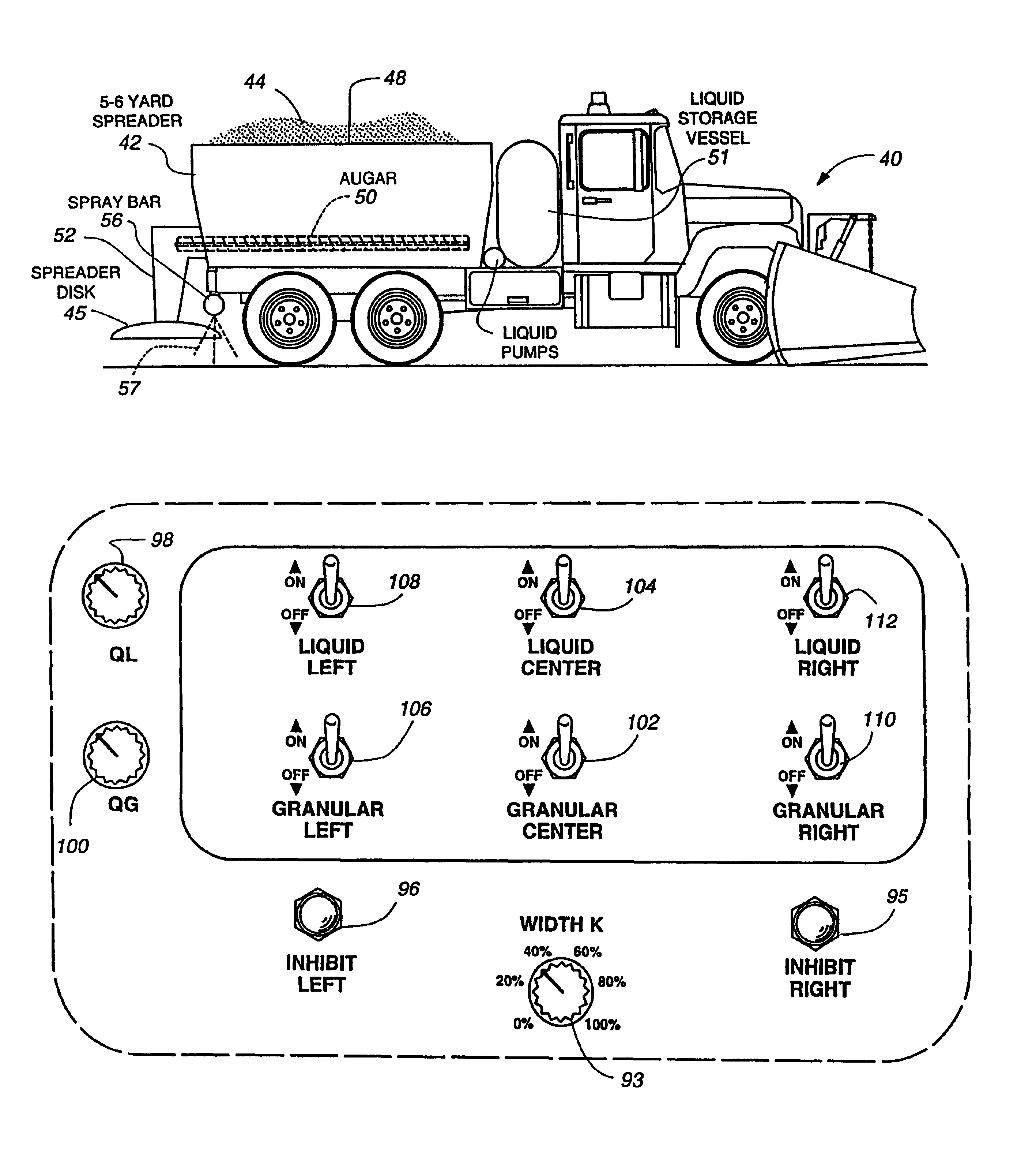
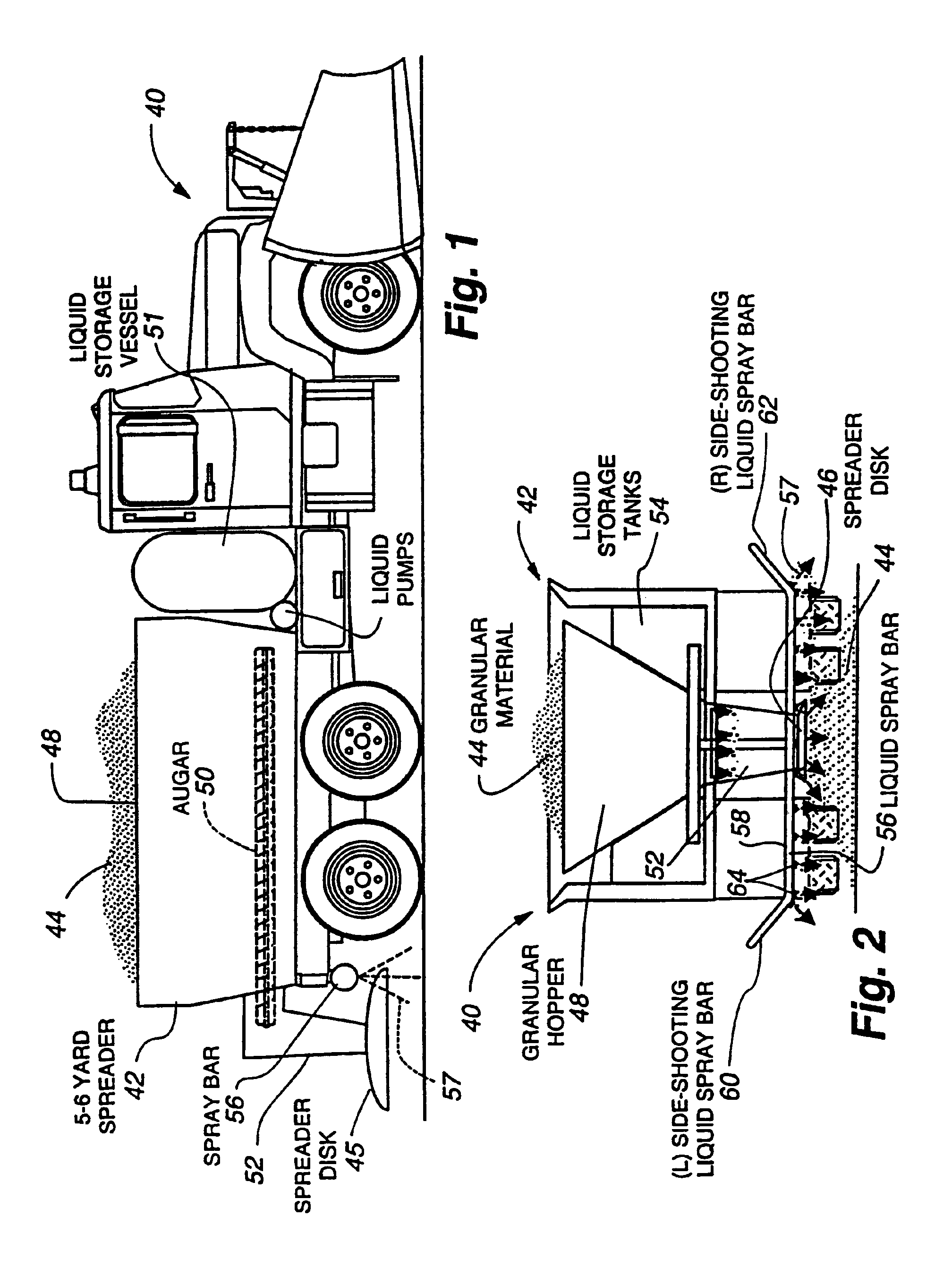
[0031]Referring to FIG. 1, a snow plow vehicle 40 incorporating the synchronized-width material spreader system 42 in accordance with the present invention is shown. The snow plow vehicle 40 includes a system for storing and spreading granular material, as well as a system for storing and spreading liquid material. While the vehicle could include multiple systems for storing and dispensing several individual types of fluid materials, for the purposes of clarity, the description herein is based on a vehicle having the capability of storing and dispensing only two different materials. In this particular example, there is one granular fluid material and one liquid fluid material. It is to be understood that there may be more than two materials as well as any combination of granular and / or liquid materials.

[0032]Further, the synchronized-width material spreader of the present invention as described in this specification is used in the environment of controlling snow and ice on roadways ...

second embodiment

[0068]Turning now to FIG. 4, with the granular material 44 as the trigger material, the control box 91 is disclosed. The control knob 93 controls the width of spread of any and all materials which are enabled. The Inhibit right control knob 95 will inhibit any enabled material from being spread to the right side of the carrier regardless of the spread-width selected on control knob 93. The control knob 98 controls the rate of liquid disbursement through the spray bar 56 to the road surface (for instance gallons per lane mile). The control knob 100 controls the rate of granular material 44 disbursement to the road surface (for instance pounds per lane mile). The granular material dispensing means and the liquid material dispensing means are controlled by each appropriate switch: center 102, 104; left 106, 108; and right 110, 112 on the control box 91. These switches allow the operator to selectively turn on and off as desired the spread of material in any of these regions.

[0069]Turni...

third embodiment

[0078]Referring now to FIGS. 9 and 10, a block diagram of a remote surface condition sensing and control apparatus in the invention is shown for providing real time surface condition information to the vehicle operator and to the on board computer 216 utilized to automatically control the material spread on the vehicle roadway surface. This third embodiment is a completely automatic sensing and material application apparatus 200 which is mounted on the vehicle 40. The local sensing portion is shown in FIG. 9. The control and remote component connections are shown in FIG. 10. The sensing portion of the system 200 includes at least one electromagnetic radiation transceiver 202 which emits a ultra-wide band (UWB) impulse radar. A very short electromagnetic (EMR) impulse is propagated from transceiver 202 and echoes that reflect from the road surface 204 and from material on the road surface are evaluated. These reflected signals are set to a depth processor 206, a density processor 208...


PUM


Abstract

An apparatus and system, preferably mounted on a service vehicle, provides synchronized application of fluid materials, either solid or liquid, to a vehicle travel surface in proportional amounts or spatially distributed proportions in response to user defined requirements and/or operation of a vehicle mounted component in response to conditions encountered in real time. A first embodiment is a vehicle mounted apparatus and system for coordinated application of a plurality of materials to a surface simultaneously and in desired proportions and/or widths automatically and/or selectively. A second embodiment includes a granular material distribution device and includes a plurality of liquid spray headers and pumping means. A third embodiment of the present invention is a vehicle mounted apparatus and system for automated coordinated application of a plurality of materials to a surface as well as automated component control such as blade blocking plate control based on sensed current surface condition information and current accurate location information as well as past operating history and predicted near term weather conditions.

Description

CROSS REFERENCE TO RELATED APPLICATIONS[0001]This application is continuation of Ser. No. 09 / 643,154 filed Aug. 21, 2000, now abandoned, which is a continuation of Ser. No. 09 / 286,809 filed Apr. 6, 1999, now U.S. Pat. No. 6,173,904, which is a continuation of Ser. No. 08 / 879,921 filed Jun. 20, 1997 now U.S. Pat. No. 5,904,296, which is a continuation-in-part of U.S. patent application Ser. No. 08 / 783,556, filed Jan. 14, 1997, now U.S. Pat. No. 5,745,051 which is a continuation of application Ser. No. 08 / 660,232, filed Jun. 7, 1996 and now U.S. Pat. No. 5,619,193. This application also claims the benefit of U.S. Provisional Patent Application Ser. No. 60 / 020,237, filed Jun. 21, 1996 and No. 60 / 031,036, filed Nov. 18, 1996.BACKGROUND OF THE INVENTION[0002]1. Field of the Invention[0003]This invention relates generally to surface conditioning vehicles such as those carrying material spreaders and / or snow removal devices, and more particularly relates to a new and improved apparatus for...

Claims


Application Information

Patent Timeline
IPC IPC(8): A01C17/00B60T8/172B60T8/00B60T8/17B60R16/02E01C19/00E01H5/06E01C19/21E01H10/00E01H5/04G01N1/02E01C19/20B60R16/023
CPCA01C17/00B60R16/0237B60T8/00B60T8/172E01C19/004E01C19/21E01H5/066E01H10/007G01N1/02E01C2019/208G01N2001/021G01N2001/028
Inventor DOHERTY, JOHN A.KALBFLEISCH, CHARLES A.
Owner WEATHER INSIGHTS
Why Eureka
Try Eureka