Cover slip mixing apparatus

a technology of glass cover and support assembly, which is applied in the direction of positive displacement liquid engines, glassware laboratories, machines/engines, etc., can solve the problems of unfavorable data quality, unfavorable data quality, and small amount of reagents and analytes used, so as to improve the quality of mixing action, eliminate gradients, and improve data quality

Inactive Publication Date: 2005-09-06
NEW ERIE SCI LLC
View PDF35 Cites 52 Cited by
  • Summary
  • Abstract
  • Description
  • Claims
  • Application Information

AI Technical Summary

Benefits of technology

[0007]The present invention provides a mixing apparatus that substantially improves the quality of a mixing action. The mixing apparatus of the present invention causes a mixing action that eliminates gradients or conjugates that occur in nonmixed solutions. The mixing apparatus of the present invention allows conjugates and other elements in...

Problems solved by technology

Second, hybridization reactions will occur in the presence of large quantities of molecules similar but not identical to the target.
With these devices, there is a problem of hybridization non-uniformity due to formation of concentration gradients ...

Method used


Image

  • Cover slip mixing apparatus
  • Cover slip mixing apparatus
  • Cover slip mixing apparatus

Examples


second embodiment

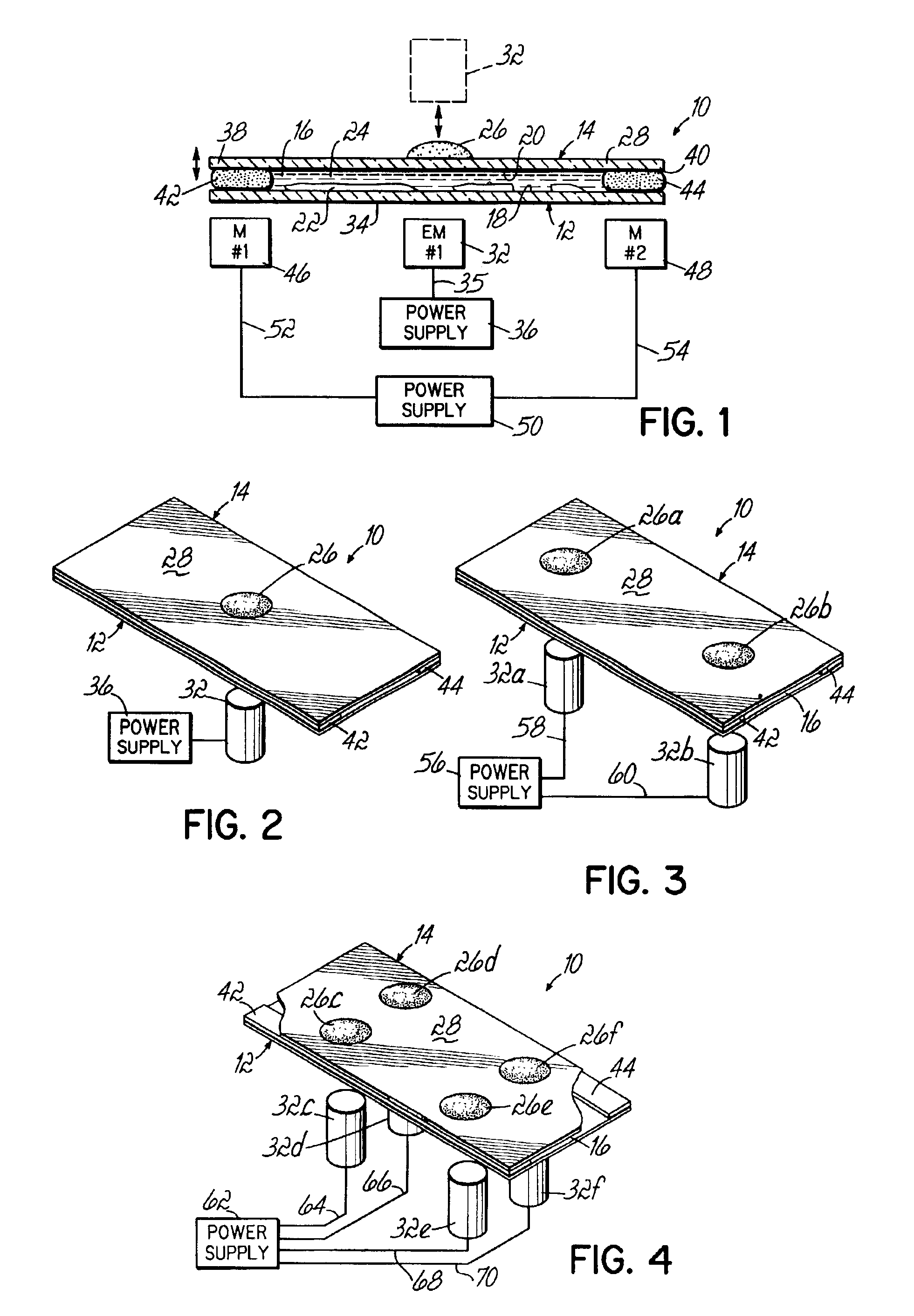
[0026]In the cover slip mixing apparatus 10 illustrated in FIG. 3, two magnetizable components 26a, 26b are located on the cover slip outer surface 28. A power supply 56 is electrically connected via outputs 58, 60 to first and second electromagnets 32a, 32b. The electromagnets 32a, 32b are located with respect to the magnetic components 26a, 26b such that when energized by the power supply 56, the electromagnets 32a, 32b induce a magnetic field in respective magnetizable components 26a, 26b. The output current from the power supply 56 can be controlled such that the electromagnetic fields from the respective electromagnets 32a, 32b produce mechanical forces on the magnetizable components 26a, 26b that are in-phase. Such forces cause portions of the cover slip 14 under the magnetic components 26a, 26b to move substantially simultaneously in the same direction. Such in-phase motion of those portions of the cover slip 14 will produce a first mixing action in the chamber 16.

[0027]A dif...

third embodiment

[0028]Referring to FIG. 4, in the cover slip mixing apparatus 10, a first pair of magnetizable components 26c, 26d are located on one half of the cover slip outer surface 28, and a second pair of magnetizable components 26e, 26f are located on the other half of the cover slip outer surface 28. A power supply 62 is electrically connected to electromagnets 32c, 32d, 32e, 32f, via respective outputs 64, 66, 68, 70. The electromagnets 32c, 32d, 32e, 32f are located with respect to the magnetic components 26c, 26d, 26e, 26f such that when energized by the power supply 62, the electromagnets 26c, 26d, 26e, 26f induce a magnetic field in the respective magnetizable components 26c, 26d, 26e, 26f.

[0029]Any pair of the electromagnets 32c, 32d, 32e, 32f can be operated in unison so that a respective pair of the magnetizable components 26c, 26d, 26e, 26f provide a greater flexing force on those portions of the cover slip 14 beneath the pair of magnetic components being operated in unison. Such...

fourth embodiment

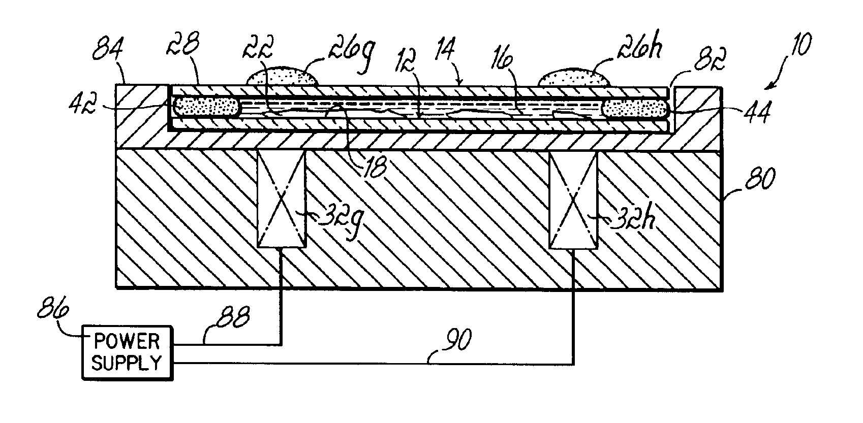
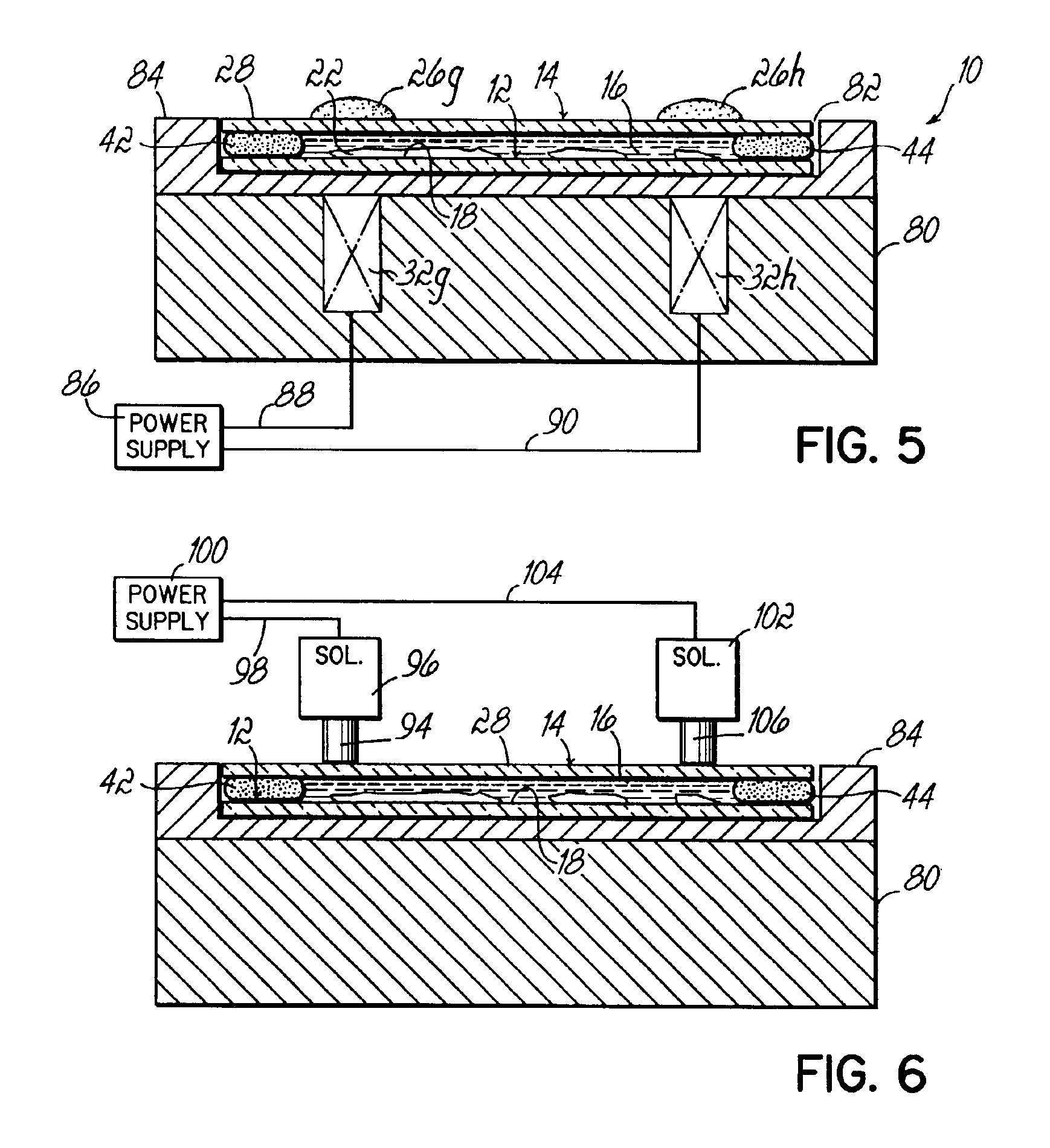
[0030]FIG. 5 illustrates the cover slip mixing apparatus 10. A base 80 is made from any nonmagnetic rigid material, for example, aluminum or plastic. A cavity 82 is formed in an upper surface 84 of the base 80. The cavity 82 is sized to receive a support 12 and cover slip 14. One or more magnetizable components 26g, 26h are located on the cover slip outer surface 28. A power supply 86 is electrically connected via outputs 88, 90 to one or more electromagnets 32g, 32h. The electromagnets 32g, 32h are located with respect to the magnetic components 26g, 26h such that when energized by the power supply 86, the electromagnets 32g, 32h induce a magnetic field in respective magnetizable components 26g, 26h. The power supply 86, electromagnets 32g, 32h and magnetic components are operated as described with respect to the other embodiments in order to provide a desired mixing action within the chamber 16.

[0031]Referring to FIG. 1, the cover slip 14 can be maintained stationary on the suppor...


PUM


Abstract

A cover slip mixing apparatus having a support and a flexible cover slip positioned over and forming a chamber between the support and the cover slip. A device is positioned with respect to the support and cover slip for applying a force on the cover slip and flexing the cover slip toward the support, the flexing cover slip providing a mixing action of a material located in the chamber. A microfluidic device includes a substrate with a fluid path disposed in the substrate. A flexible cover is positioned over the substrate and the fluid path, and a device is positioned with respect to the substrate and the cover. The device is operable to apply forces to the cover and flex the cover to act on fluid in the fluid path.

Description

[0001]This application claims the benefit of U.S. Provisional Application No. 60 / 336,282, entitled “Cover Slip Mixing Apparatus and Method”, filed Oct. 25, 2001.FIELD OF THE INVENTION[0002]This invention relates to a glass cover slip and support assembly used in hybridization methods that provides mixing of the hybridization solution.BACKGROUND OF THE INVENTION[0003]Molecular searches use one of several forms of complementarity to identify the macromolecules of interest among a large number of other molecules. Complementarity is the sequence-specific or shaped-specific molecular recognition that occurs when two molecules bind together. Complementarity between a probe molecule and a target molecule can result in the formation of a probe-target complex. This complex can then be located if the probe molecules are tagged with a detectible entity such as a chromophore, fluorophore, radioactivity, or an enzyme. There are several types of hybrid molecular complexes that can exist. A single...

Claims


Application Information

Patent Timeline
IPC IPC(8): B01F13/00B01F11/00
CPCB01F11/0045B01F13/0059B01F2215/0037B01F2215/0073B01F31/31B01F33/30B01F2101/23B01F2101/44
Inventor COSBY, N. GUYMOORE, DAVID J.CLEMENTS, JIM
Owner NEW ERIE SCI LLC
Why Eureka
Try Eureka