
Ambient air pollution trap

a technology for air pollution and ambient air, which is applied in the direction of machine/engine, combustion-air/fuel-air treatment, and separation processes, etc., can solve the problems of burning pollutants and destroying remaining pollutants, and achieve the effect of lowering the temperatur

Inactive Publication Date: 2005-09-06
FORD GLOBAL TECH LLC
View PDF19 Cites 9 Cited by
  • Summary
  • Abstract
  • Description
  • Claims
  • Application Information

AI Technical Summary

Benefits of technology

The invention is a method for removing pollutants from the air in a vehicle by using an adsorption unit. The adsorption unit is designed to remove pollutants from the air when the vehicle is stationary, by using a fan to draw air through the system. The pollutants are then released when the vehicle is in motion, and the air is heated before being released. The method helps to clean the air in the vehicle and reduces the amount of pollutants released from the vehicle's exhaust system. The invention also includes a regeneration system for the adsorption unit, which can be initiated when the pollutant levels in the air exceed a certain level or when the vehicle is in motion. The regeneration system uses the existing ventilation system of the vehicle, with minimal alterations, to clean the air.

Problems solved by technology

In this way the pollutants can be burnt in a combustion chamber of the engine and any remaining pollutants may be destroyed in the existing catalytic converter of the vehicle exhaust system.

Method used


Image

  • Ambient air pollution trap
  • Ambient air pollution trap
  • Ambient air pollution trap

Examples


Embodiment Construction

[0025]In the following text a number of embodiments will be described in detail. When describing the direction of the flow of air, the terms “upstream” and “downstream” are defined to apply to the instantaneous direction of flow. Because the direction of flow is reversed between adsorbing and desorbing modes, a first device may be placed upstream of a second device in the adsorbing mode and downstream of the same device in the desorbing mode.

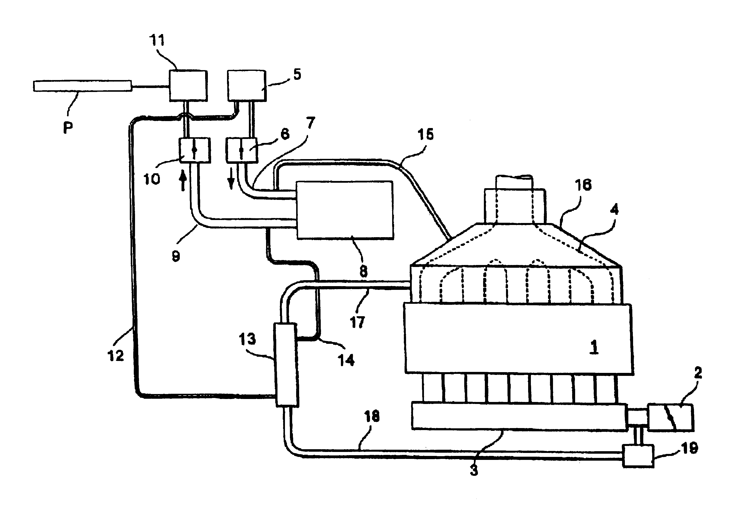
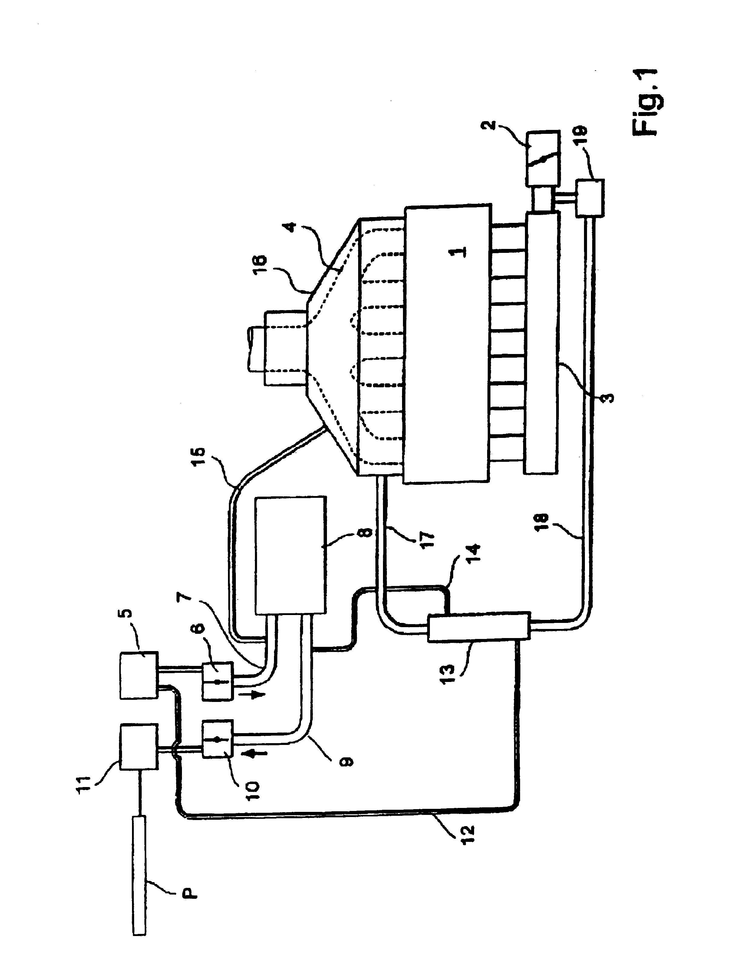
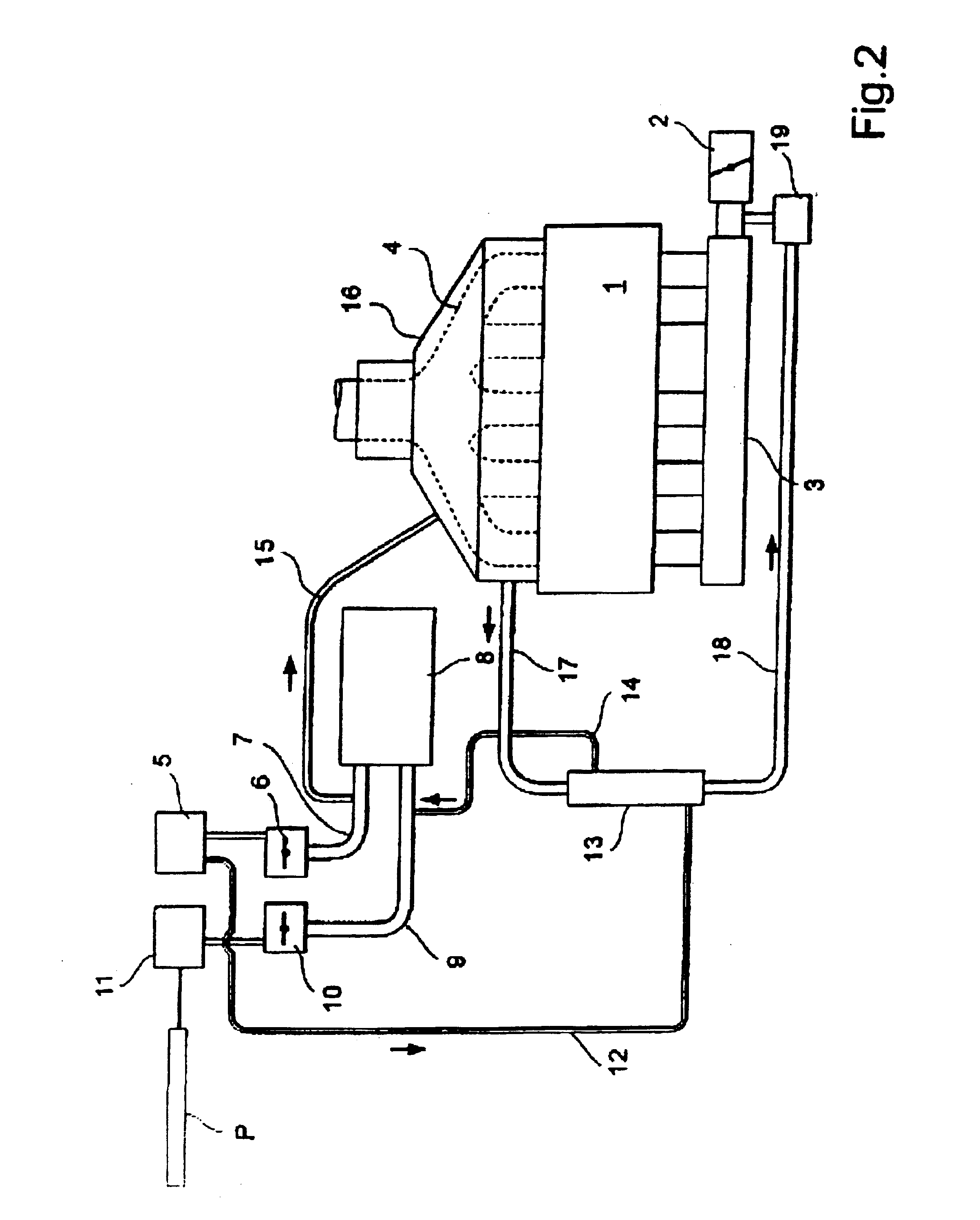
[0026]The description below describes a method and an apparatus for removing pollutants, such as hydrocarbon compounds, from ambient air by means of an adsorption unit arranged in a ventilation system for a passenger compartment in a vehicle provided with a combustion engine.

[0027]FIG. 1 shows a multicylinder internal combustion engine 1 with an intake conduit provided with a main throttle 2. From the throttle 2, intake air passes through an inlet manifold 3 connected to each cylinder. The combusted exhaust gases leave the engine through an exha...


PUM

PropertyMeasurementUnit
temperatureaaaaaaaaaa
temperaturesaaaaaaaaaa

Abstract

The invention relates to a method and an apparatus for cleaning ambient air of a vehicular adsorption unit (8). The vehicle includes a combustion engine (1) and a passenger ventilation system (5, 6, 7, 8, 9, 10, 11). Adsorption takes place whether the engine (1) is running or not. During adsorption, a fan (11) forces ambient air from an inlet (6) to the ventilation system in a first direction, through an adsorption unit (8), and out of an outlet (10). To desorb when the engine is running, air is supplied to a heater (13). Heated air is passes through the adsorption unit (8) to release pollutants and regenerate the unit. Pollutant containing air passes through a second heater (4, 16) and then through the first heater (13) to heat the ambient air. Finally, polluted air is drawn from the heat exchanger (13) to an intake conduit (3) of the engine (1).

Description

FIELD OF THE INVENTION[0001]The current invention relates to a method for removing pollutants, such as hydrocarbon compounds, from ambient air by an adsorption unit arranged in a vehicle provided with a combustion engine and a ventilation system for a passenger compartment.BACKGROUND OF THE INVENTION[0002]Recent methods have instead been aimed at purifying ambient air and polluted air from other vehicles. U.S. Pat. No. 6,200,542 discloses a method for breaking down ozone. According to the known method, a catalytic coating is applied to the radiator and other surfaces in the engine compartment. When the ozone comes into contact with these surfaces it is converted to oxygen.[0003]A further known method, described in EP 1082990, uses a HC trap adjacent to the radiator for adsorbing pollutants from the ambient air while the vehicle is moving. The adsorbing process is followed by desorption by passing heated intake air through the trap to an intake conduit of the engine. This apparatus i...

Claims


Application Information

Patent Timeline
Patent Type & Authority Patents(United States)
IPC IPC(8): B01D53/04B01D53/92B60H3/06
CPCB01D53/04B01D53/0415B01D53/92B60H3/0633B01D53/0438B01D53/0446B01D2253/102B01D2253/108B01D2257/106B01D2257/402B01D2257/404B01D2257/502B01D2257/70B01D2257/702B01D2258/01B01D2258/012B01D2258/06B01D2259/40003B01D2259/40009B01D2259/40081B01D2259/4009B01D2259/4516B01D2259/4558B01D2259/4566B60H2003/0691Y02C20/10
Inventor PETERSSON, MARTINKARLSSON, JAN KE
Owner FORD GLOBAL TECH LLC
Learn More