Optical measurement apparatus and method for optical measurement

a technology of optical measurement and optical measurement, which is applied in the direction of optical radiation measurement, instruments, tubes with screens, etc., can solve the problems of extremely small amount of data stored in the storing portion, digital oscilloscope has a higher resolution than, and drastically limited the length of time of oscilloscope, etc., to achieve the effect of extremely small amount of data stored in the storing step

Inactive Publication Date: 2005-09-06
HAMAMATSU PHOTONICS KK
View PDF24 Cites 13 Cited by
  • Summary
  • Abstract
  • Description
  • Claims
  • Application Information

AI Technical Summary

Benefits of technology

[0007]The optical measurement apparatus can measure when photons have arrived by storing a time signal that is outputted from the time signal outputting portion when the photon detecting portion detects photons. On the other hand, no data is stored in the storing portion when the photon detecting portion does not detect photons. Accordingly, the amount of data stored in the storing portion is extremely small. As a result, the optical measurement apparatus can measure, over a long period of time, when photons have arrived.
[0009]The optical measurement apparatus can measure when and how many photons have arrived by storing, when the photon detecting portion detects photons, the number of the photons detected by the photon detecting portion and a time signal that is outputted from the time signal outputting portion when the photon detecting portion detects photons. On the other hand, no data is stored in the storing portion when the photon detecting portion does not detect photons. Accordingly, the amount of data stored in the storing portion is extremely small. As a result, the optical measurement apparatus can measure over a long period of time when and how many photons have arrived.
[0013]By using the photon detecting portion that is provided with the photocathode, the accelerating portion, and the semiconductor photodetector, it is possible to efficiently detect the number of photons that fall incident simultaneously (or at nearly the same timings).
[0018]The optical measurement method can measure when and how many photons have arrived by storing, when the photon detecting step detects photons, the number of the photons detected by the photon detecting step and a time signal that is outputted at the time signal outputting step when the photon detecting step detects photons. On the other hand, no data is stored by the storing step when the photon detecting step does not detect photons. Accordingly, the amount of data stored by the storing step is extremely small. As a result, the optical measurement method can measure over a long period of time when and how many photons have arrived.

Problems solved by technology

However, because the oscilloscope is not designed for detecting photons, the digital oscilloscope has a higher resolution than necessary.
Accordingly, as a tradeoff for the high resolution, the oscilloscope is drastically limited in the length of time that the oscilloscope can perform measurements.
Accordingly, the amount of data stored in the storing portion is extremely small.

Method used


Image

  • Optical measurement apparatus and method for optical measurement
  • Optical measurement apparatus and method for optical measurement
  • Optical measurement apparatus and method for optical measurement

Examples


Embodiment Construction

[0030]An optical measurement apparatus and method for optical measurement according to a preferred embodiment of the present invention will be described with reference to FIGS. 1–4(c).

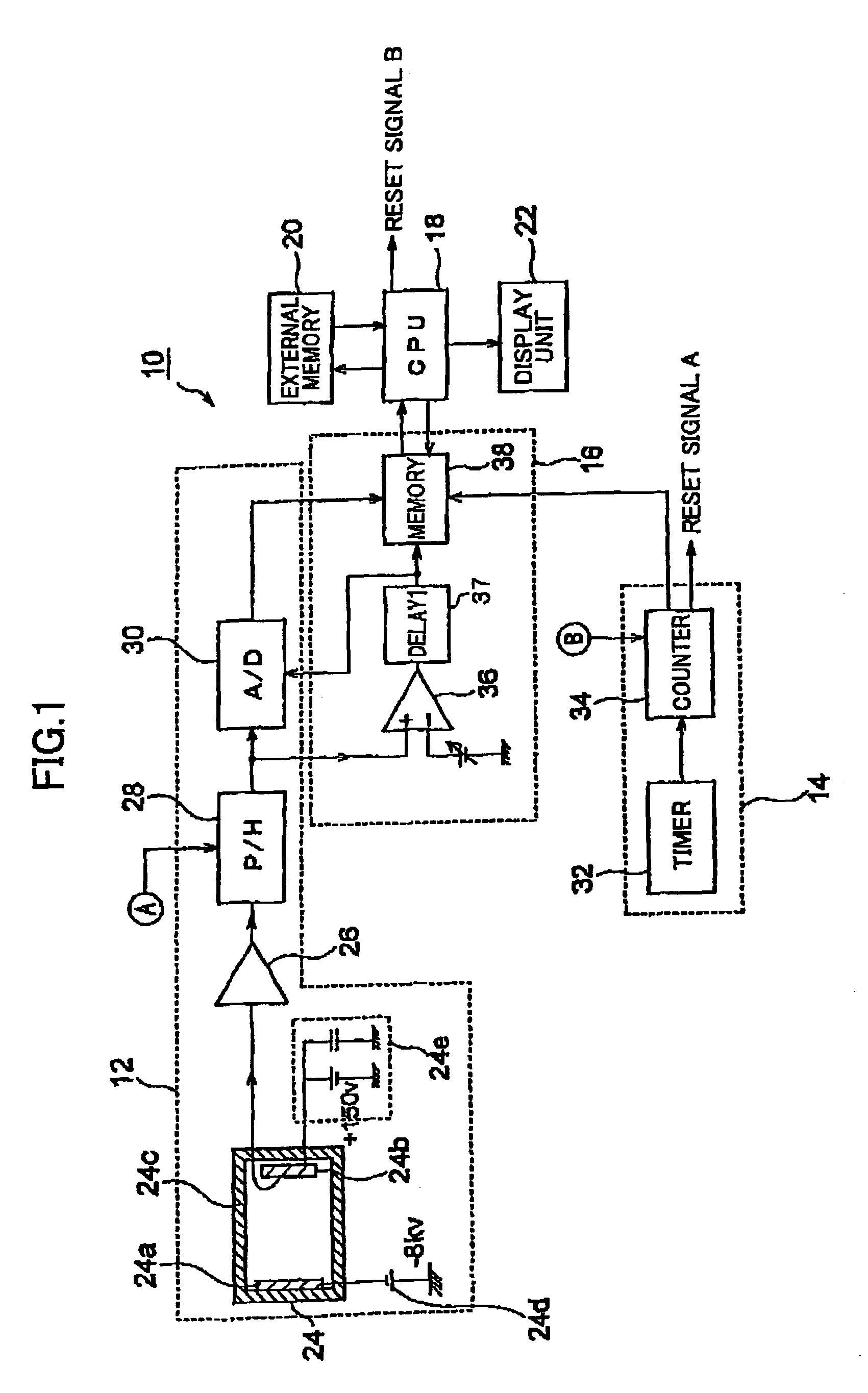
[0031]First the construction of the optical measurement apparatus according to the preferred embodiment will be described. FIG. 1 shows the construction of this optical measurement apparatus.

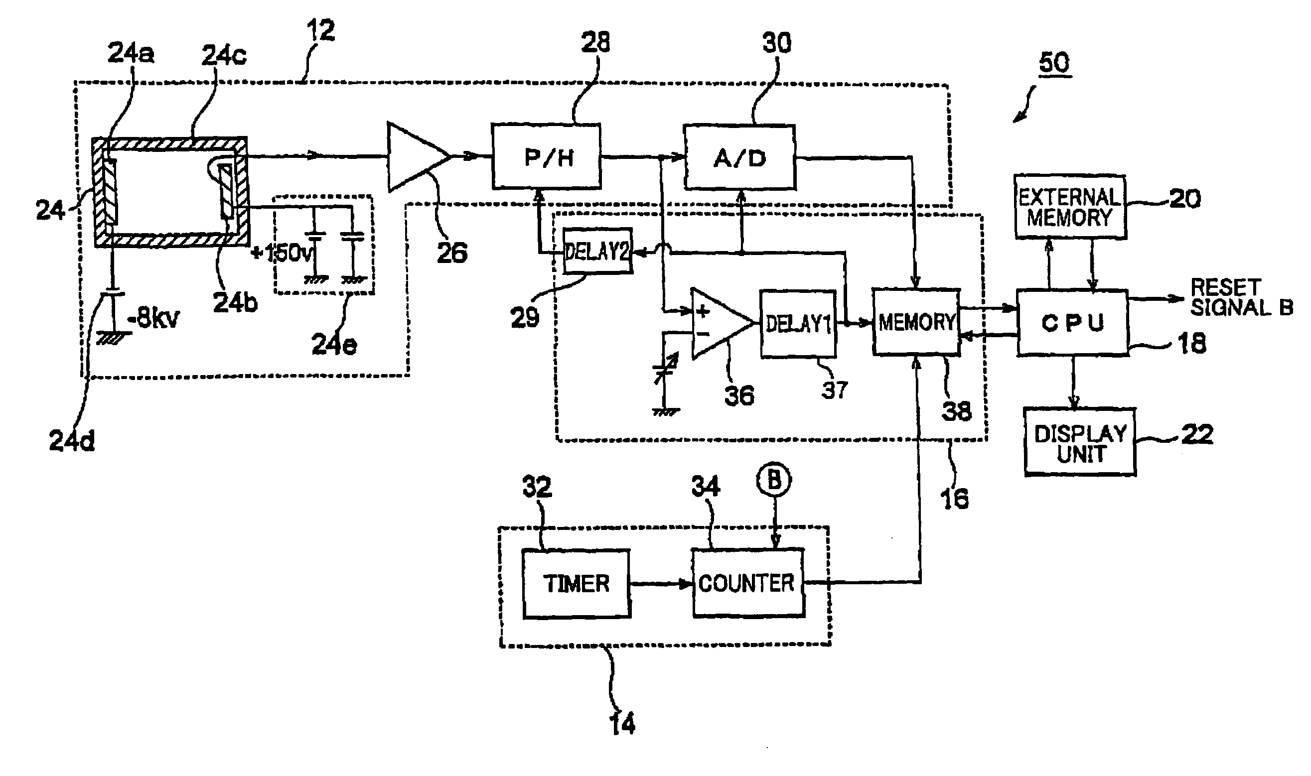
[0032]An optical measurement apparatus 10 according to the preferred embodiment includes a photon detection unit 12 for detecting incident photons, a time signal output unit 14 for outputting a time signal, a storage unit 16 for storing time signals outputted from the time signal output unit 14 when the photon detection unit 12 detects photons, a CPU 18 for controlling overall operations of the device, an external memory 20 for storing settings and the like, and a display unit 22 for displaying measurement results and the like. Next, each component of the optical measurement apparatus 10 will be described in more d...


PUM


Abstract

An optical measurement apparatus 10 primarily includes: a photon detection unit 12 for detecting incident photons, a time signal output unit 14 for outputting a time signal, and a storage unit 16 for storing the time signal outputted from the time signal output unit 14 when the photon detection unit 12 detects photons. The photon detection unit 12 includes a HPD 24 having a photocathode 24a and an APD 24b, a TZ amplifier 26, a peak holding circuit 28, and an A / D converter 30. The time signal output unit 14 includes a timer 32 and a counter 34. The storage unit 16 includes a comparator 36 and a memory 38. When photons impinge on the HPD 24, a trigger signal is outputted from the comparator 36, causing the photon-number outputted from the A / D converter 30 and the time data outputted from the counter 34 to be stored in the memory 38.

Description

TECHNICAL FIELD[0001]The present invention relates to an optical measurement apparatus and a method for optical measurement, and particularly to an optical measurement apparatus and method for optical measurement for detecting photons.BACKGROUND ART[0002]Accompanying the development of optical technology in recent years, light has come to be used in such fields as optical communications, optical sensing, and optical computers, and there is no doubt that these fields of use will continue to expand in the future. Under these conditions, the measurement of light has become extremely important. Tools used for measuring light, such as photomultiplier tubes and the like, are well known in the art. By using the photomultiplying effect of photomultiplier tubes, it is possible to detect weak light with great efficiency.[0003]However, in order to expand the new fields for using optics in the future, it will be extremely important to measure light at the photon level in time and space, as in “...

Claims


Application Information

Patent Timeline
Patent Type & Authority Patents(United States)
IPC IPC(8): G01J1/44
CPCG01J1/44G01J2001/442G01J2001/4433G01J2001/444G01J2001/4466
Inventor SUYAMA, MOTOHIROKAWAI, YOSHIHIKOMORITA, TETSUYAOBA, KOICHIRO
Owner HAMAMATSU PHOTONICS KK
Why Eureka
Try Eureka