Internally coolable screw

Inactive Publication Date: 2005-09-13
SIEMENS AG
View PDF9 Cites 15 Cited by
  • Summary
  • Abstract
  • Description
  • Claims
  • Application Information

AI Technical Summary

Benefits of technology

[0014]The advantages of an embodiment of the invention lie in particular in the fact that, by avoiding a coolant flow which passes axially through the entire screw, firstly especially effective utilization of the coolant can be achieved, in particular by coolant w

Problems solved by technology

If the screw or a part of the screw, in particular the screw head, due to a failure of said screw, gets into the combustion chamber and is entrained by the gas flow, serious damage to the downstream turbine is

Method used


Image

  • Internally coolable screw
  • Internally coolable screw
  • Internally coolable screw

Examples


Embodiment Construction

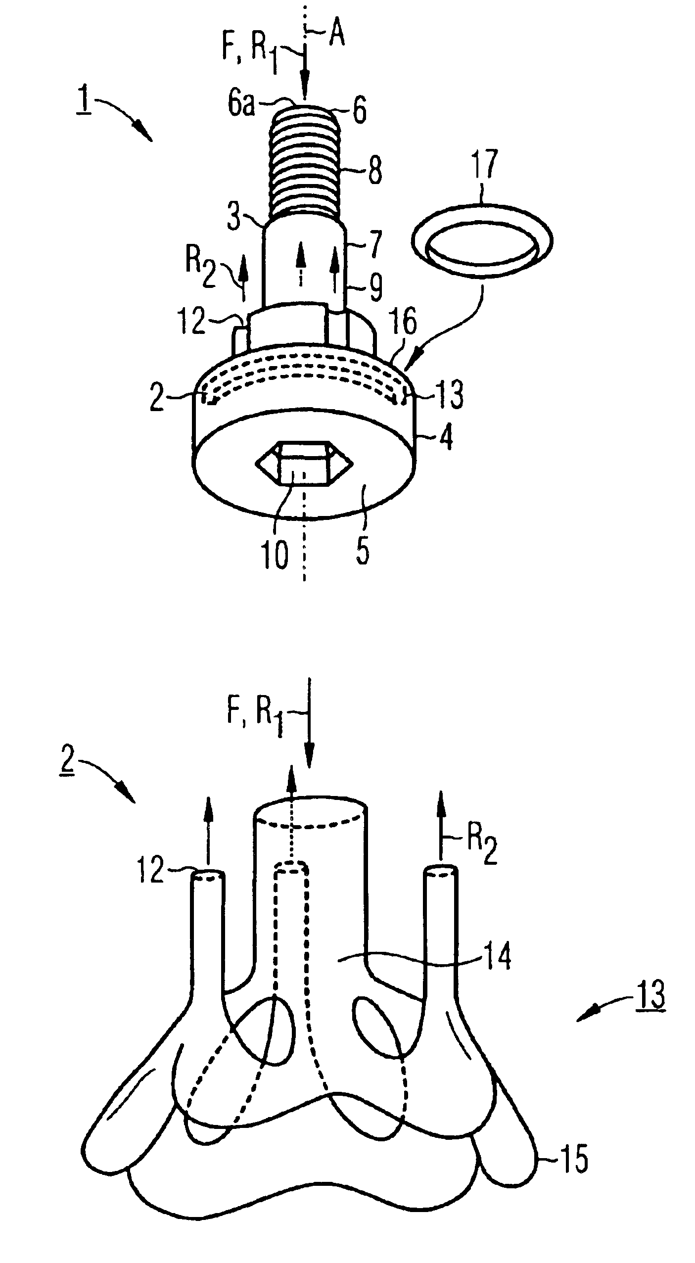
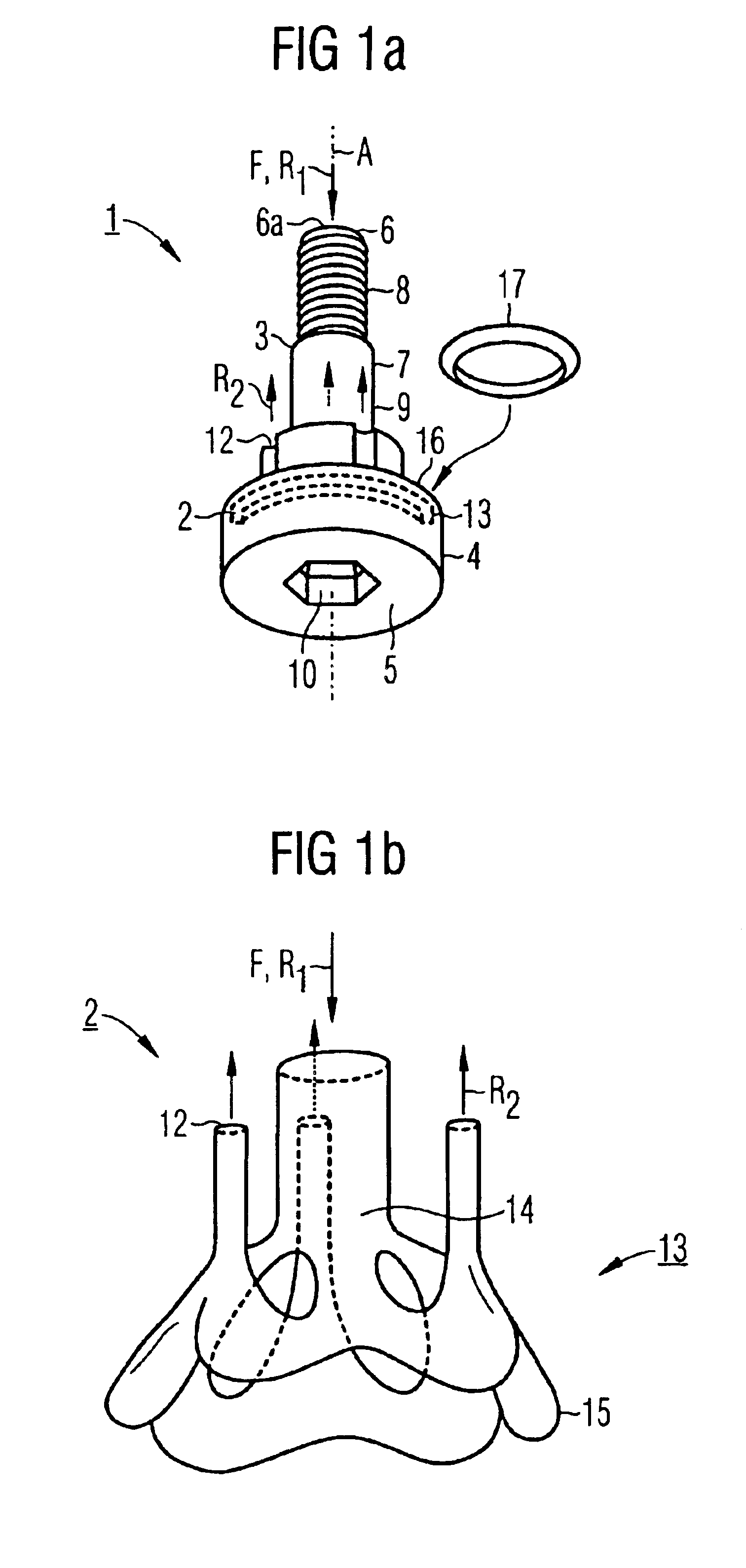
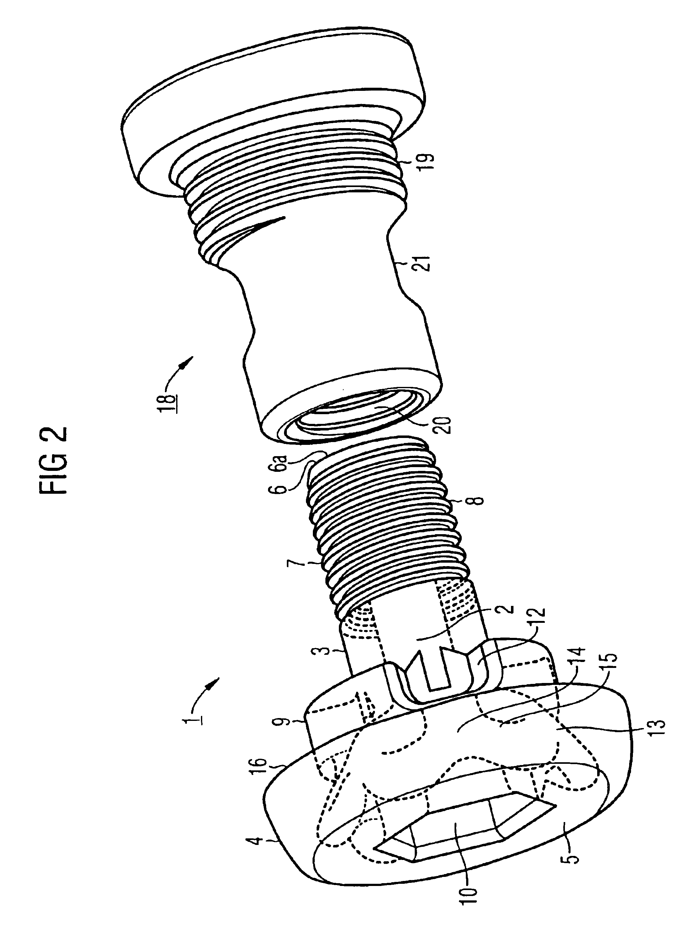
[0020]FIG. 1a shows an internally coolable screw 1, the coolant passage or cooling passage 2 of which is shown as a cutaway detail in FIG. 1b. The screw 1 has a shank 3 and a head 4 and extends along an axis or axis of symmetry A from a top surface 5, lying at the bottom in the representation, of the head 4 up to a shank end 6. The shank 3, with a shank circumference 7, has a thread 8 and a screw collar 9 of thickened design defining the shank 3 toward the head 4. On its top surface 5, the head 4 has a hexagonal actuating opening 10 for a hexagon socket key.

[0021]A coolant or cooling fluid F flows axially at the shank end 6 in inflow direction R1 into an inflow opening 6a of the screw 1 and discharges from the latter at three coolant-outflow openings or outflow openings 12 in outflow direction R2, which is opposed to the inflow direction R1. The cooling passage 2 runs first of all coaxially in the shank 3 and, in the head 4, assumes the course indicated by broken lines in FIG. 1a an...


PUM


Abstract

A screw includes a head and a shank, and includes a coolant passage which has an inflow opening and an outflow opening. The cooling pasage does not pass axially through the entire head and shank. By avoiding a coolant flow which passes axially through the entire screw, especially effective utilization of a coolant is achieved, in particular by coolant which also flows on the outer surface of the screw.

Description

[0001]The present application hereby claims priority under 35 U.S.C. §119 on European patent application number EP 02018492.5 filed Aug. 16, 2002, the entire contents of which are hereby incorporated herein by reference.FIELD OF THE INVENTION[0002]The invention generally relates to a screw which can be internally cooled by a flowing coolant.BACKGROUND OF THE INVENTION[0003]Screws subjected to high mechanical and thermal loads are used, for example, in gas turbine construction. An example of application is the fastening of a combustion-chamber inner lining to a wall of a combustion chamber.[0004]It is normally attempted to operate a gas turbine with as high a temperature as possible in the combustion chamber in order to achieve a high efficiency. Gas temperatures of 1200° C. to 1300° C. are typically achieved at the outlet of the combustion chamber. The combustion-chamber inner lining is often fastened to the combustion-chamber wall with screws inserted from the inside, i.e. from the...

Claims


Application Information

Patent Timeline
IPC IPC(8): F16B33/00F16B35/06F16B35/04F01D25/12F02C7/18F16B35/00F23R3/42F23R3/60
CPCF16B33/00F16B35/04F16B35/044F16B35/06F23R3/60
Inventor TIEMANN, PETER
Owner SIEMENS AG
Why Eureka
Try Eureka