Hybrid reheat system with performance enhancement

Active Publication Date: 2005-09-13
CARRIER CORP
View PDF4 Cites 63 Cited by
  • Summary
  • Abstract
  • Description
  • Claims
  • Application Information

AI Technical Summary

Benefits of technology

[0010]In further features, an economizer cycle is incorporated into the system and can be selectively utilized in conjunction with the reheat

Problems solved by technology

This has presented design challeng

Method used


Image

  • Hybrid reheat system with performance enhancement
  • Hybrid reheat system with performance enhancement
  • Hybrid reheat system with performance enhancement

Examples


Embodiment Construction

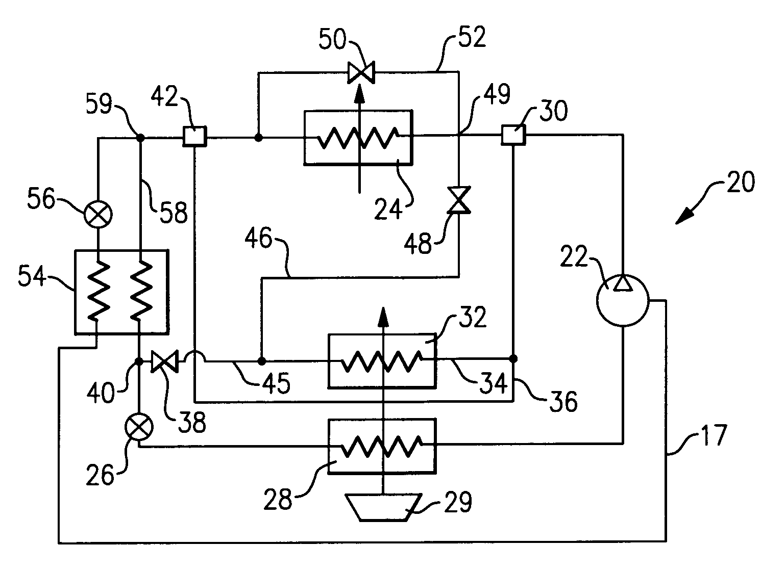
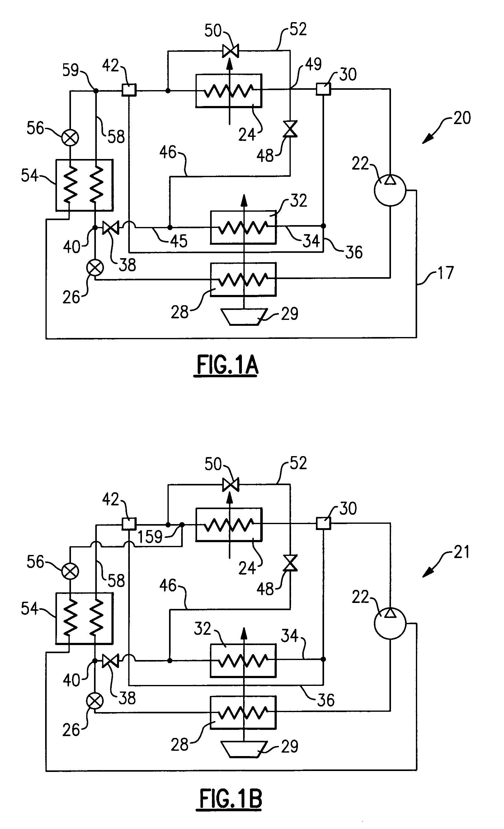
[0016]The refrigerant system 20 is illustrated in FIG. 1A. Refrigerant system 20 includes a compressor 22 delivering a compressed refrigerant into a discharge line. Downstream of the compressor 22 a condenser 24 receives the compressed refrigerant. As is known, a main expansion device 26 is positioned downstream of the condenser, and the refrigerant flows through the main expansion device to an evaporator 28. As is also known, an air moving device, such as a fan 29, blows air over the evaporator 28 and into an environment to be conditioned. The refrigerant returns to the compressor 22 from the evaporator 28.

[0017]The above is a brief description of the main features of known refrigerant cycles. The present invention offers greater control over the parameters of the conditioned air stream as well as enhanced flexibility in system operation and design than those provided in the prior art. In particular, a first three-way valve 30 selectively communicates refrigerant in the line downst...


PUM


Abstract

An economizer loop is incorporated into the refrigerant system, which in conjunction with any selected reheat mode of operation, provides augmented performance, improved reliability, and enhanced control in meeting external heat load demands. A refrigerant system includes several features that can be selectively utilized alone or in combination with each other to provide an enhanced control over system cooling and dehumidification capability. In particular, a reheat coil is incorporated into the refrigerant system, and has alternative connection points to the main circuit, positioned both upstream and downstream of a condenser. Also, a flow control device allows a selective bypass around a condenser. In this manner, the refrigerant flowing through the reheat coil can be controlled to provide a desired level of temperature and humidity. Finally, the compressor may include an unloader feature such that additional steps in capacity control can be provided.

Description

BACKGROUND OF THE INVENTION[0001]This application relates to a refrigerant system having a variety of operational features. In particular, a reheat coil is incorporated and can selectively receive a refrigerant flow from a location either upstream or downstream of a condenser to provide precise control over system operation characteristics. In further features, an economizer circuit is incorporated into the system, to selectively function in conjunction with the reheat coil, as well as the ability to bypass the condenser is provided.[0002]This application relates to refrigerant systems that incorporate both an economizer cycle concept and a reheat coil to provide better dehumidification performance and temperature control in response to variable latent and sensible heat load demands.[0003]Refrigerant systems are utilized to control the temperature and humidity of air in various environments. In a typical refrigerant cycle, a refrigerant is compressed in a compressor and delivered to...

Claims


Application Information

Patent Timeline
IPC IPC(8): F25B41/00F24F3/153F25B41/04
CPCF24F3/153F25B41/04F25B2400/13F25B2600/0261F25B41/20F25B41/24
Inventor TARAS, MICHAEL F.LIFSON, ALEXANDER
Owner CARRIER CORP
Why Eureka
Try Eureka