
Anchor for marine mooring

a technology for anchors and marine structures, applied in anchors, vessel construction, construction, etc., can solve the problems of limiting the mooring line direction, difficult embedding, and not allowing the anchor to dig deeper

Active Publication Date: 2005-09-13
DELMAR SYST
View PDF5 Cites 17 Cited by
  • Summary
  • Abstract
  • Description
  • Claims
  • Application Information

AI Technical Summary

Benefits of technology

This design enables deeper embedment in stronger seabed soils, increasing holding capacity and eliminating orientation concerns during installation, as the anchor can rotate to achieve optimal orientation and penetration.

Problems solved by technology

These anchors have major disadvantages in that they are difficult to embed to deep penetrations below the seabed, where the underlying soils are stronger and thus can provide greater holding capacity.
One disadvantage with the existing designs is that the behavior of the anchor under increasing loading does not allow the anchor to dig deeper into the stronger soils typically encountered at greater penetrations.
Another disadvantage of the prior art anchors involves limits placed on the mooring line direction (that is, loads in a direction radially outward from the anchor shaft) unless the attachment line is placed at the top of these anchors; such top placement severely limits the anchor's holding capacity.
Such orientation (that is, orienting the attachment point in a desired radial direction) may be very difficult to accurately achieve.

Method used


Image

  • Anchor for marine mooring
  • Anchor for marine mooring
  • Anchor for marine mooring

Examples


Embodiment Construction

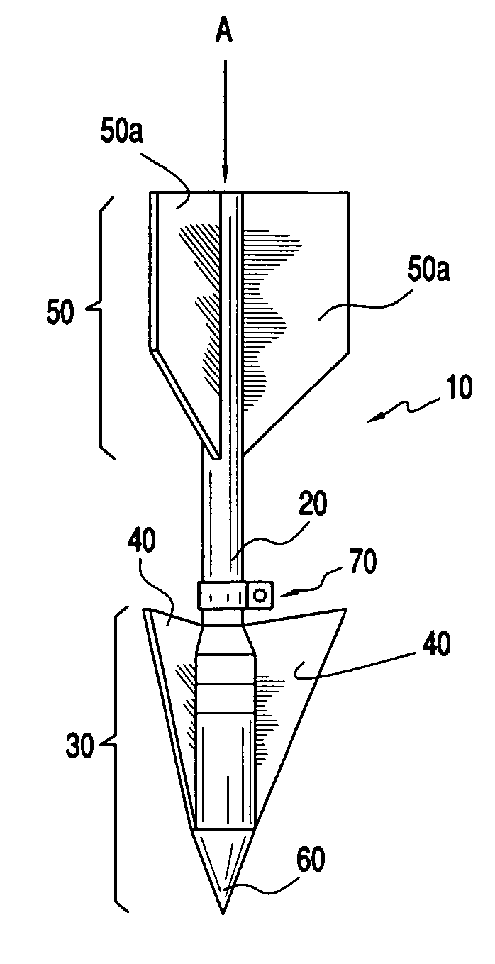
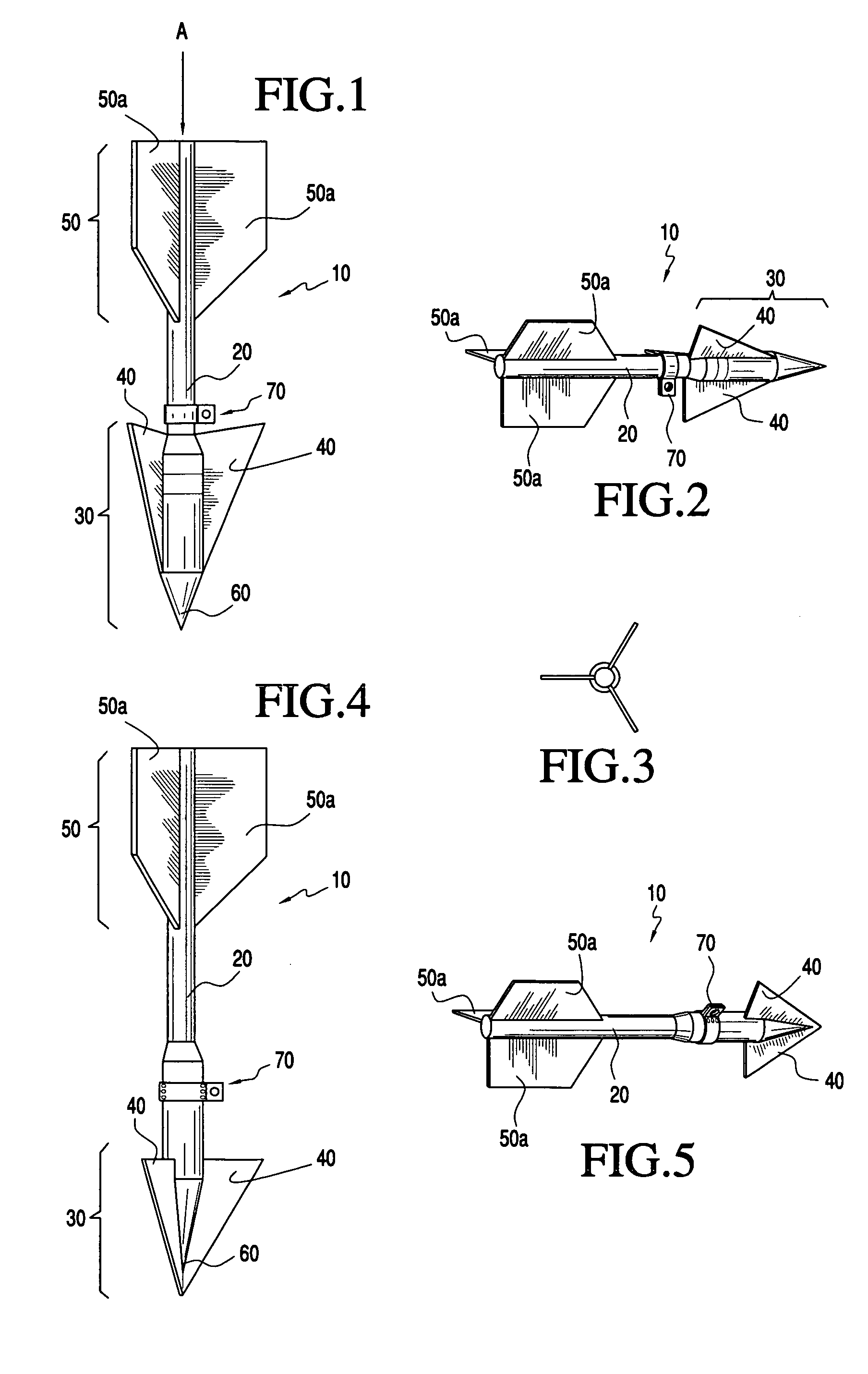
[0017]Several of the primary structural attributes of the anchor of the present invention are first generally described. Such attributes can be modified and configured to suit particular applications.

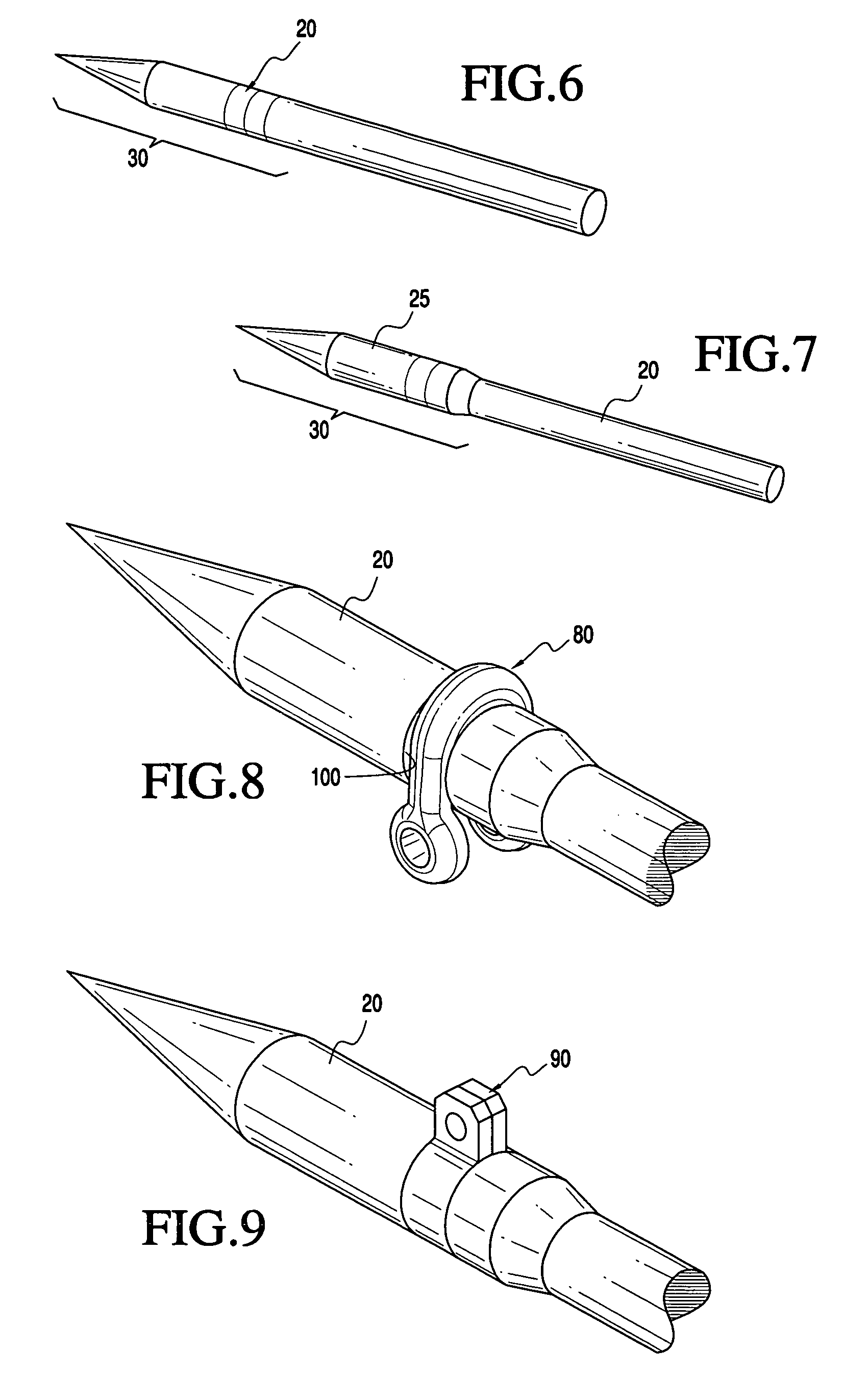
[0018]1. Anchor shaft. The shaft may be designed with a larger outer diameter over the lower section (proximal to the nose section of the anchor) to both add mass, lower the center of gravity and reduce relative frictional resistance on the upper section while the anchor is penetrating the soil. In one embodiment of the anchor, the anchor shaft terminates in a pointed cone in the nose section (i.e. the lower end), and the nose section fins do not extend beyond the base of the cone, greater soil penetration can generally be achieved due to reduced frictional soil forces developing on the point.

[0019]2. Radial fins. Similar to the holding attributes of a plate type anchor, the radial fins of the present anchor provide a majority of the soil resistance needed for the anchor holding capacit...


PUM


Abstract

Anchor for mooring of buoyant marine structures. The anchor comprises an elongated shaft with a mooring line attachment that is rotatable around the full circumference (that is, a full 360 degrees of rotation) of the anchor shaft. The lower end of the shaft comprises nose section, while the upper end comprises a tail section. A plurality of fins are attached to the nose section and tail section, and extend radially outward from the anchor shaft. While the number of fins may vary, one presently preferred embodiment has three fins in each section of the anchor shaft. The anchor is preferably configured (via design of the nose and tail section fin areas, shapes, etc., and the location of the mooring line attachment along the anchor shaft) such that less soil resistance is created on the nose section than on the tail section under the influence of a mooring line load, so that the anchor will rotate slightly about the mooring line attachment point under the applied load while penetrating deeper into the soil underlying the seabed.

Description

CROSS REFERENCES TO RELATED APPLICATIONS[0001]This application claims priority for all purposes to provisional patent application Ser. No. 60 / 515,744, filed Oct. 30, 2003.BACKGROUND[0002]1. Field of Invention[0003]This invention relates to apparatus and method for mooring of marine structures. With more particularity, this invention relates to an anchor especially (although not exclusively) suitable for gravity installation, which embeds itself in a seabed by virtue of being dropped from a height above the seabed and being allowed to fall to the seabed of its own weight, and methods of installation of such anchor.[0004]2. Description of Prior Art[0005]A large suite of different anchor designs have evolved over the decades that rely on the anchor to embed or to be drug into the seabed to develop the holding capacity for the required mooring line load. These anchor designs vary widely in form or shape, from a caisson or pile to a conventional drag embedment anchor that includes flukes...

Claims


Application Information

Patent Timeline
Patent Type & Authority Patents(United States)
IPC IPC(8): B63B21/26B63B21/24B63B21/22B63B21/00
CPCB63B21/26B63B21/22B63B2021/262B63B2021/265
Inventor ZIMMERMAN, EVAN H.SMITH, MATTHEW W.YOUNG, ALAN G.
Owner DELMAR SYST
Learn More