
Grommeted bypass duct penetration

a bypass duct and duct sealing technology, applied in the direction of cable terminations, liquid fuel engine components, piston engines, etc., can solve the problems of not being able to accommodate thermal expansion and contraction

Inactive Publication Date: 2005-09-13
PRATT & WHITNEY CANADA CORP
View PDF28 Cites 27 Cited by
  • Summary
  • Abstract
  • Description
  • Claims
  • Application Information

AI Technical Summary

Benefits of technology

[0007]The invention provides a bypass duct sealing grommet, for sealing between an opening in a gas turbine engine bypass duct wall and the external surface of a projection extending through the opening. Conventionally, the intersection between the projection and the sheet metal bypass duct requires accurate fitting and welding, but cannot then accommodate thermal expansion and contraction. The grommet enables an oversized opening for accommodating relative thermal motion and simplifies manufacture. The grommet has an annular body with a central aperture adapted to seal against the external surface of the projection and two flanges defining an external slot about an exterior periphery of the body to contain and seal the bypass duct wall between the flanges.

Problems solved by technology

Conventionally, the intersection between the projection and the sheet metal bypass duct requires accurate fitting and welding, but cannot then accommodate thermal expansion and contraction.

Method used


Image

  • Grommeted bypass duct penetration
  • Grommeted bypass duct penetration
  • Grommeted bypass duct penetration

Examples


Embodiment Construction

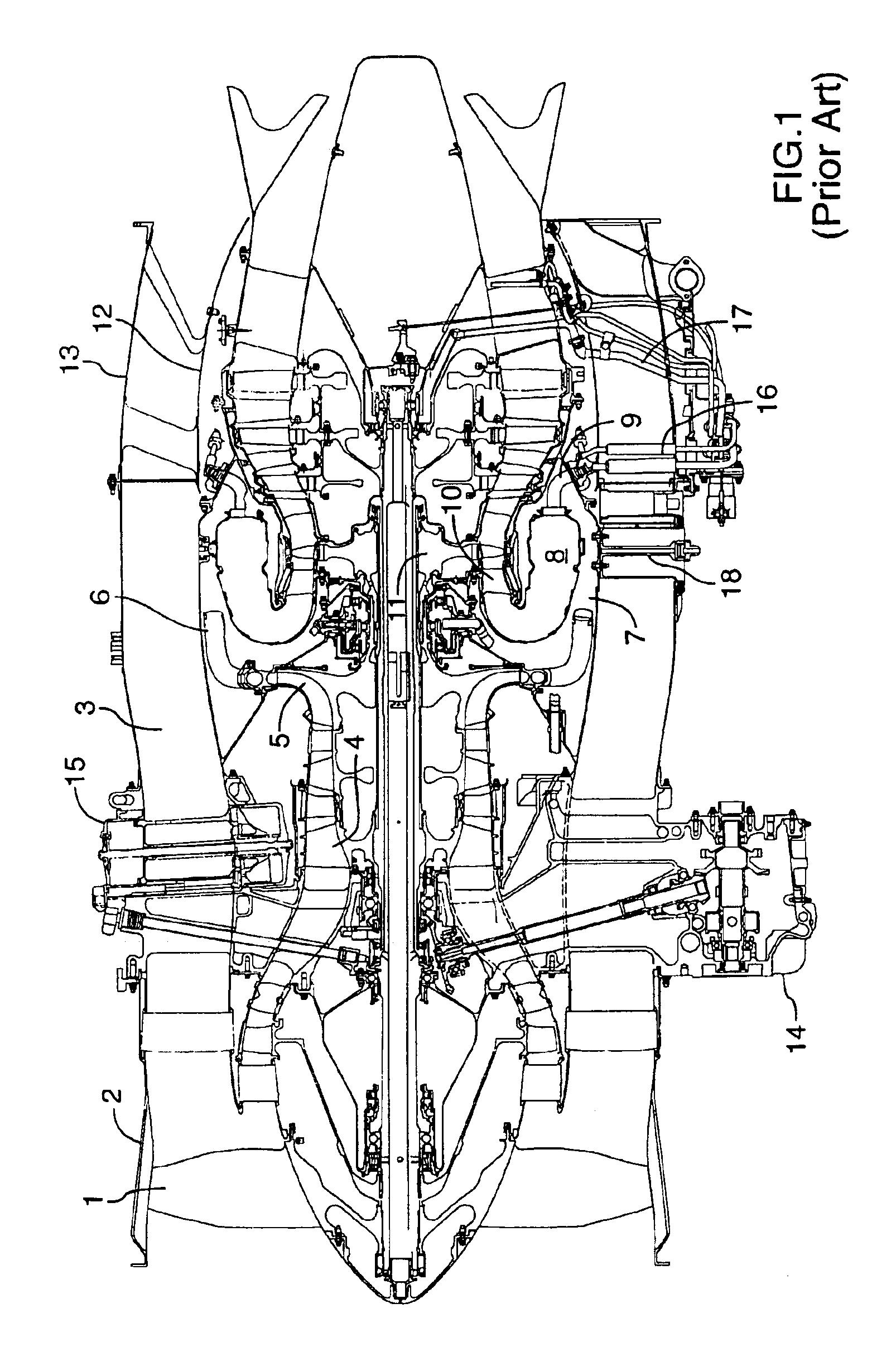
[0018]FIG. 1 shows an axial cross-section through a turbofan gas turbine engine. It will be understood however that the invention is also applicable to any type of engine with a thin-walled air duct with a penetration(s) requiring sealing. Air intake into the engine passes over fan blades 1 in a fan case 2 and is then split into an outer annular flow through the bypass duct 3 and an inner flow through the low-pressure axial compressor 4 and high-pressure centrifugal compressor 5. Compressed air exits the compressor 5 through a diffuser 6 and is contained within a plenum 7 that surrounds the combustor 8. Fuel is supplied to the combustor 8 through fuel tubes 9 which is mixed with air from the plenum 7 when sprayed through nozzles into the combustor 8 as a fuel air mixture that is ignited. A portion of the compressed air within the plenum 7 is admitted into the combustor 8 through orifices in the side walls to create a cooling air curtain along the combustor walls or is used for cooli...


PUM


Abstract

A bypass duct sealing grommet, for sealing between an opening in a gas turbine engine bypass duct wall and the external surface of a projection extending through the opening, where the grommet has an annular body with a central aperture having an interior periphery adapted to sealingly engage the external surface of the projection. A first flange and second flanges define an external slot about an exterior periphery of the body adapted to receive and seal the bypass duct wall between the flanges.

Description

TECHNICAL FIELD[0001]The invention relates to a thin-walled duct penetration sealing grommet, particularly useful for sealing between an opening in a gas turbine engine bypass duct wall and the external surface of a projection extending through the opening to simplify manufacture by eliminating complex joint configurations, while accommodating pressure differential, and relative thermal expansion and contraction.BACKGROUND OF THE ART[0002]The bypass duct of a turbofan gas turbine engine contains a pressurized flow of air between the outer duct wall and the engine core. At several locations along the length and about the circumference of the annular bypass duct, penetrations are necessary for conveying fuel, oil, control cables or compressed air bleed from the compressor to an aircraft cabin, as well as many control and monitoring penetrations for instrumentation, inspection and maintenance.[0003]In the prior art, penetrations through the bypass duct are generally accomplished by shr...

Claims


Application Information

Patent Timeline
IPC IPC(8): F01D11/00F01D9/00F01D9/06
CPCF01D9/065F01D11/005F05D2230/642Y10T16/063Y02T50/60
Inventor BRUNO, VITTORIOHADI, GOLIOLVER, BRYAN
Owner PRATT & WHITNEY CANADA CORP
Features
  • Generate Ideas
  • Intellectual Property
  • Life Sciences
  • Materials
  • Tech Scout
  • Unparalleled Data Quality
  • Higher Quality Content
  • 60% Fewer Hallucinations
Learn More