

Engine control strategy for a marine propulsion system for improving shifting
- Summary
- Abstract
- Description
- Claims
- Application Information
AI Technical Summary
Benefits of technology
Problems solved by technology
Method used
Image

Examples
Embodiment Construction
[0028]Throughout the description of the preferred embodiment of the present invention, like components will be identified by like reference numerals.
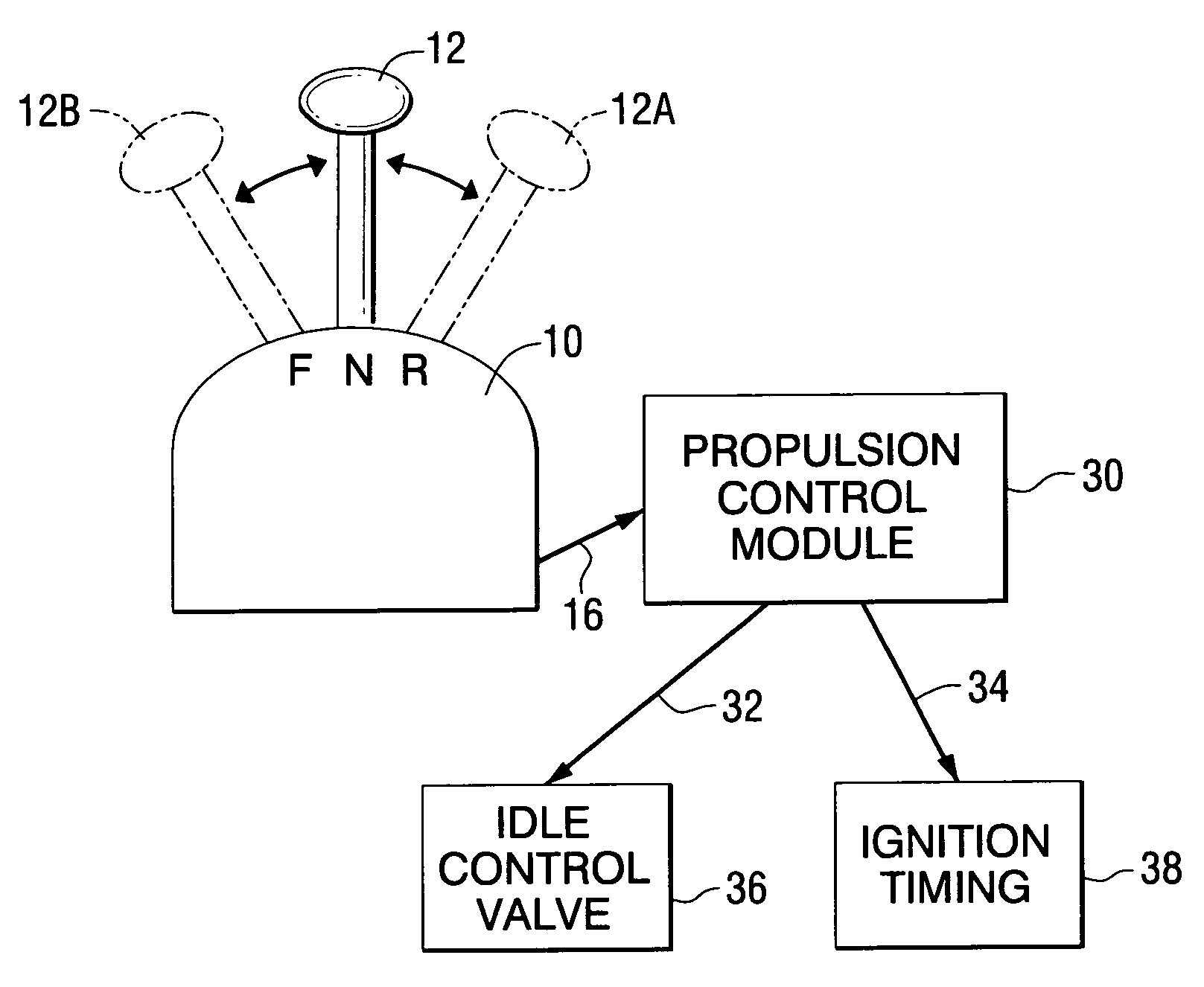
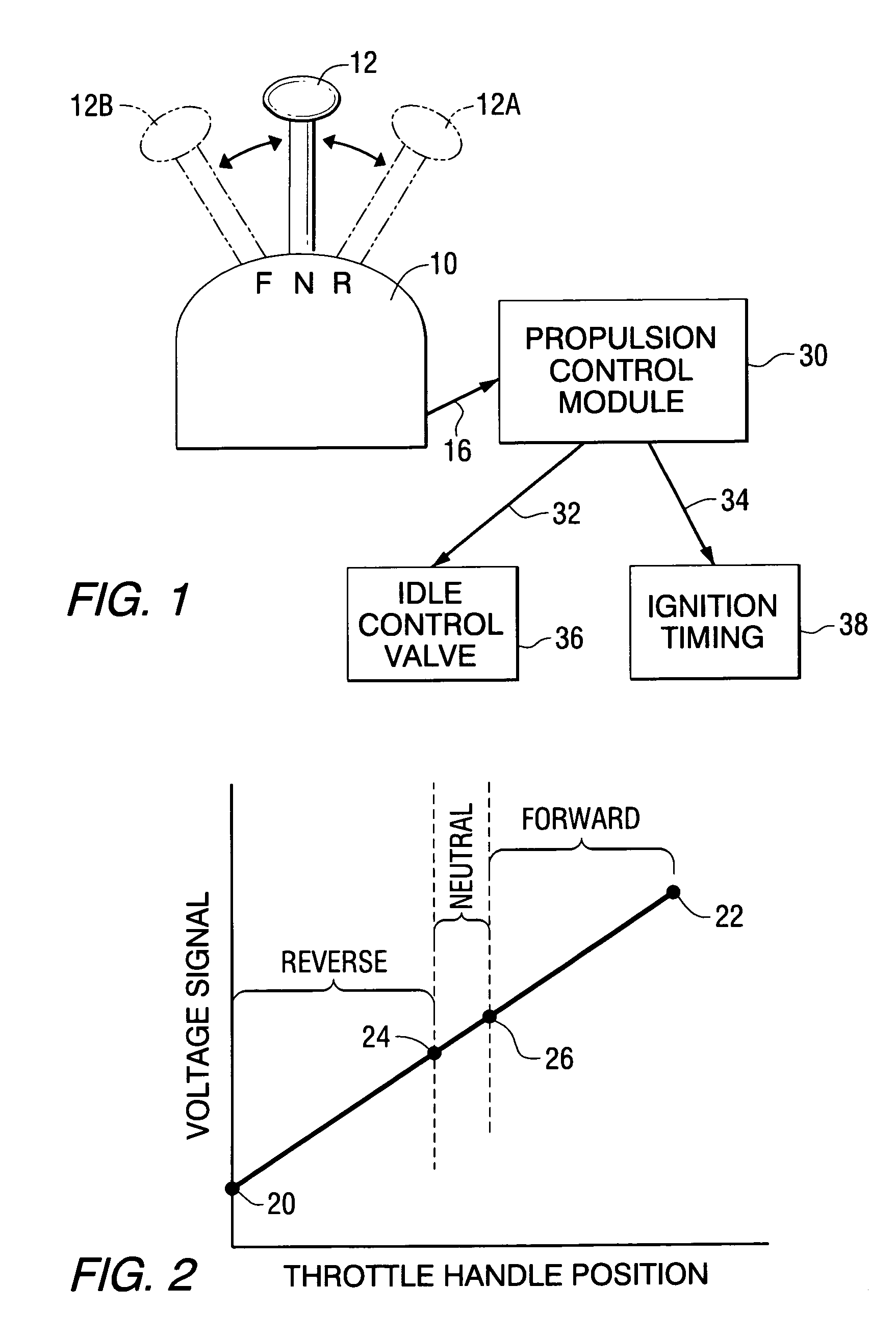
[0029]It is generally known to those skilled in the art that marine propulsion systems exhibit vibration and noise during a shift from neutral to either forward or reverse gear because of the impact of the clutch engaging at the instant when the shifting event occurs. This vibration and noise occurs whether the clutch is a cone clutch or a dog clutch. It is also generally known that engine control strategy can be used to lessen the noise when a marine propulsion transmission is shifted from either forward or reverse gear into neutral gear position. Typically, this is accomplished by interrupting the spark to one or more cylinders in order to slow the operating speed of the engine during the shifting event in which the transmission is moved into the neutral gear position from either the forward gear position or the reverse gear position....
PUM
 Abstract
Description
Claims
Application Information