
Reinforced abrasive wheels

a technology of reinforced abrasives and abrasives, which is applied in the direction of gear teeth, manufacturing tools, manufacturing apparatus for gear teeth, etc., can solve the problems of wasting a third of fiberglass cloth cutting these circles, reducing increasing the cost of manufacturing, so as to reduce the empty space, increase the strength, and save the effect of layer materials

Inactive Publication Date: 2005-09-13
SAINT GOBAIN ABRASIVES INC
View PDF42 Cites 95 Cited by
  • Summary
  • Abstract
  • Description
  • Claims
  • Application Information

AI Technical Summary

Benefits of technology

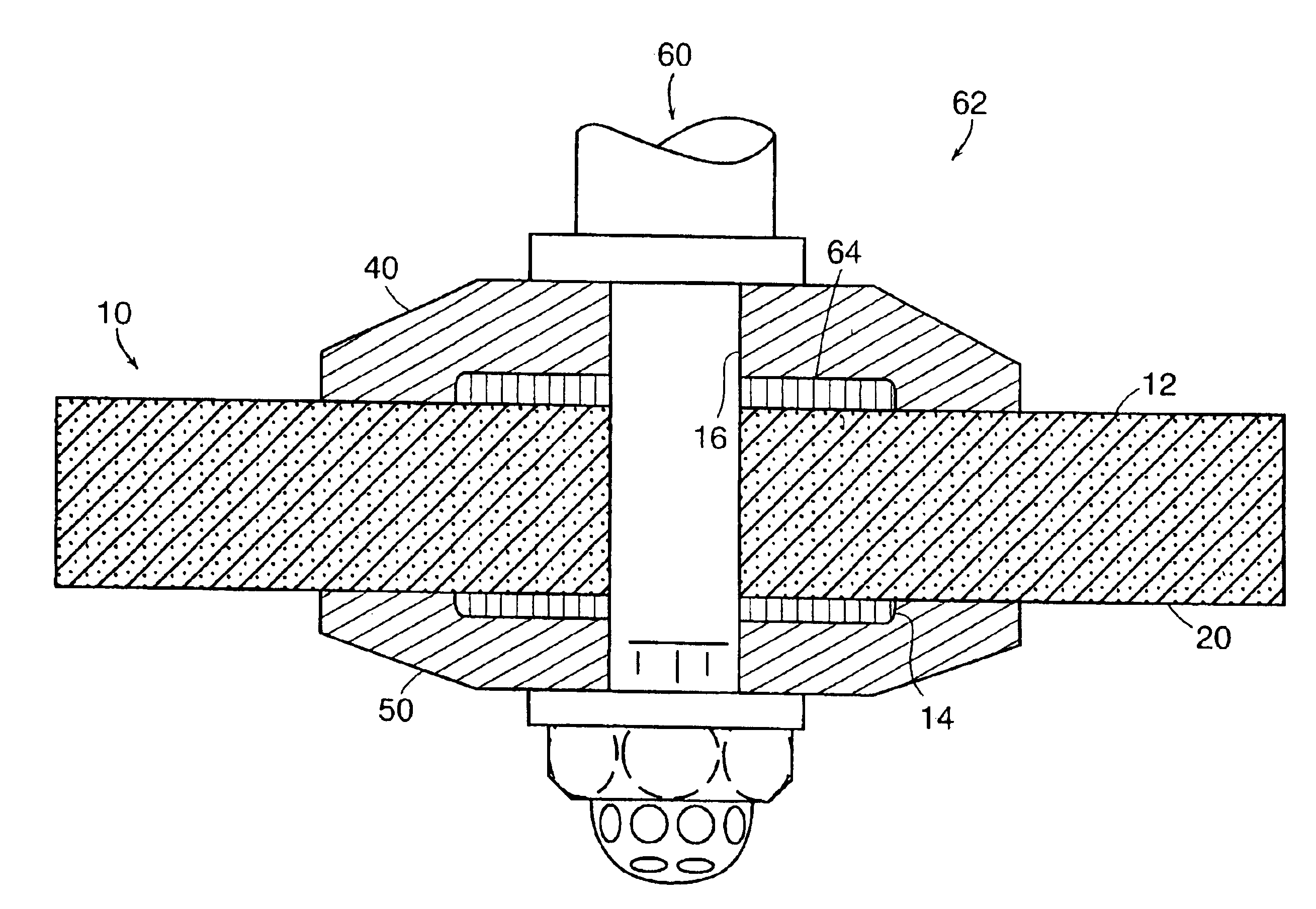
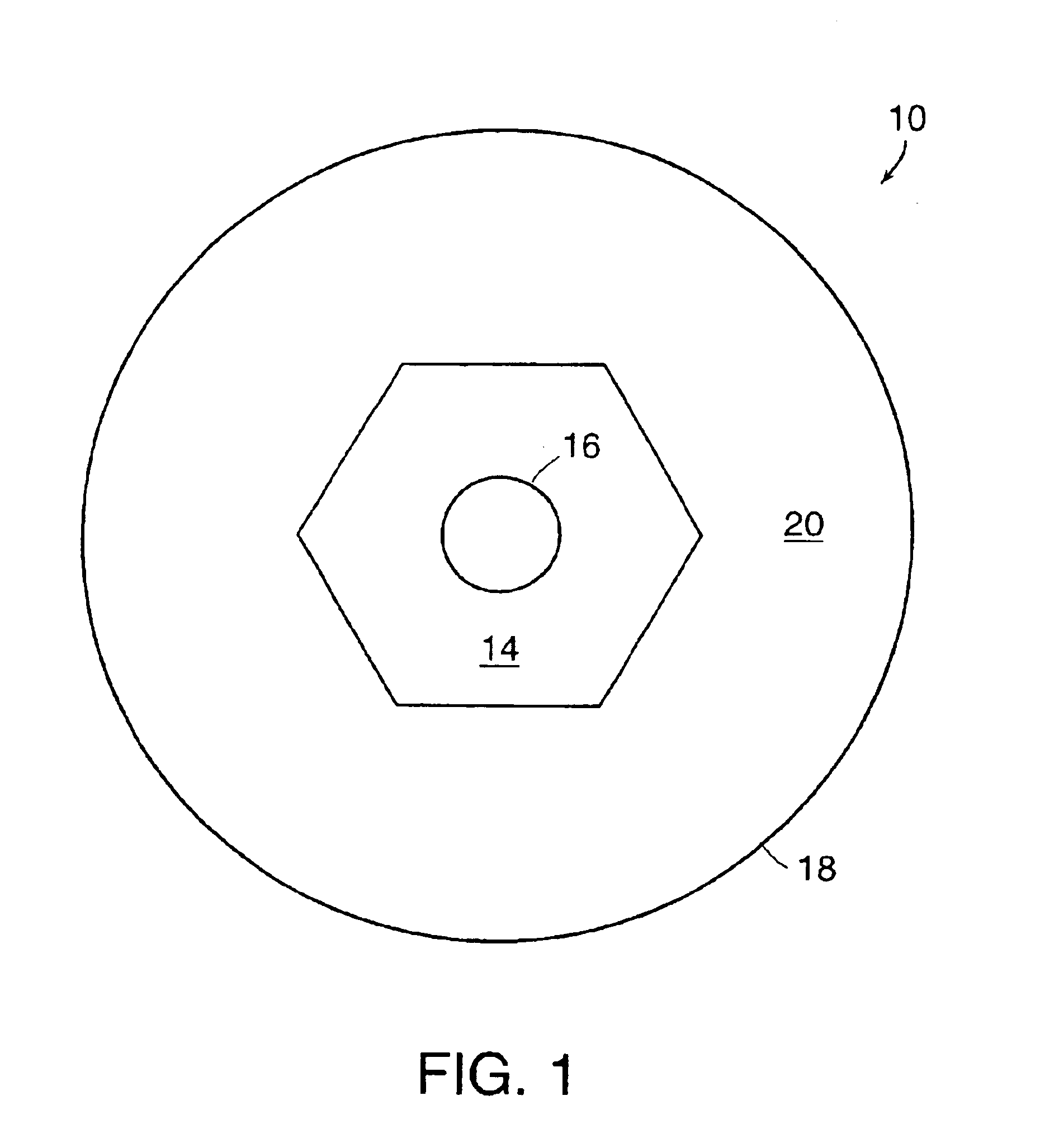
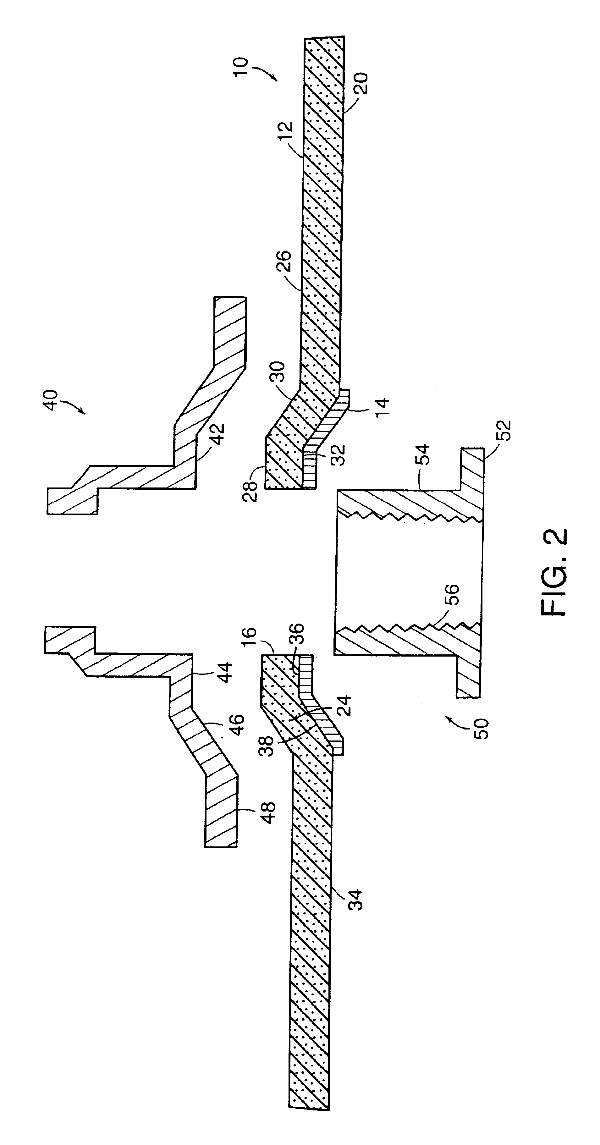
[0013]This invention has several advantages. For example, the reinforcement layer provides additional strength to the wheel assembly. The layer also forms a pad between the front flange and the depressed center of the wheel, thereby minimizing any empty space that might exist between the wheel front face and the front flange. Since the layer is 75% or less of the outer wheel diameter, savings in layer materials are obtained. Also, since the layer is typically cut from cloth, shapes such as, for example, hexagons provide significant reductions in the waste of cloth material, thereby significantly lowering the manufacturing cost of wheel assemblies.

Problems solved by technology

Furthermore, since they wear out and need to be replaced, keeping their cost of manufacturing low is also important.
Typically, about one-third of the fiberglass cloth is wasted in cutting these circles.

Method used


Image

  • Reinforced abrasive wheels
  • Reinforced abrasive wheels
  • Reinforced abrasive wheels

Examples


Embodiment Construction

[0020]The features and other details of the invention, either as steps of the invention or as combination of parts of the invention, will now be more particularly described with reference to the accompanying drawings and pointed out in the claims. The same numeral present in different figures represents the same item. It will be understood that the particular embodiments of the invention are shown by way of illustration and not as limitations of the invention. The principle feature of this invention may be employed in various embodiments without departing from the scope of the invention.

[0021]FIG. 1 is a plan view of one embodiment of the invention. As shown, abrasive wheel 10 includes front face 20. Abrasive wheel 10 can be of a flat or depressed-center type. Reinforcement layer 14 overlays front face 20 of abrasive wheel 10. Reinforcement layer 14 is concentric with abrasive wheel 10. Both abrasive wheel 10 and reinforcement layer 14 have orifice or arbor hole 16 which generally a...


PUM


Abstract

In a depressed-center abrasive wheel assembly a reinforcement layer of polygonal shape is located between a front face of the abrasive wheel and a front flange. The reinforcement layer is dimensioned to entirely cover the depressed center portion of the wheel. An example of polygonal reinforcement layer has a hexagonal shape and is made of fiberglass cloth. A polygonal shape reinforcement layer can also be employed between the front flange and the front face in an abrasive flat wheel assembly that employs a wheel without internal reinforcement.

Description

RELATED APPLICATIONS[0001]This application is a divisional of U.S. application Ser. No. 10 / 260,014, filed Mar. 20, 2003 (now U.S. Pat. No. 6,749,496), which is a continuation of U.S. application Ser. No. 09 / 364,235, filed Jul. 29, 1999, now abandoned. The entire teachings of the above application are incorporated herein by reference.BACKGROUND OF THE INVENTION[0002]Abrasive wheels are generally formed by bonding together abrasive grains or particles with a bonding material, typically a resin. Such wheels are employed in grinding operations. For example, “thin” wheels are used in cutoff and snagging operations and may be used without external cooling. Thin abrasive wheels may have no reinforcement or they may be fabric or filament reinforced. Thin abrasive wheels can have full or partial (zone) reinforcement.[0003]Both flat and depressed center abrasive wheels are available. Flat (Type 1) wheels typically are held between two flanges of equal size and mounted on the rotating spindle ...

Claims


Application Information

Patent Timeline
IPC IPC(8): B24D7/00B24D5/00B24D7/16B24D5/16
CPCB24D5/16B24D7/16
Inventor MOTA, JOSE ROBERTOALBRECHT, JEAN-MARIE
Owner SAINT GOBAIN ABRASIVES INC
Learn More