Vibration damper for overhead power lines

Inactive Publication Date: 2005-09-13
DULHUNTY POWER AUST
View PDF10 Cites 15 Cited by
  • Summary
  • Abstract
  • Description
  • Claims
  • Application Information

AI Technical Summary

Benefits of technology

[0021]In practice, it has been found that it is possible to achieve this and still obtain sufficient holding strength so that the damping weights do not fall off in service.
[0022]Advantageously, the method of attachment of the damping weight to the messenger cable according to the present invention minimises static stresses in the messenger cable at the point of attachment and hence minimises the likelihood of fatigue failure of the cable.
[0024]It is therefore important that the ends of each layer be allowed to move longitudinally in relation to the adjacent layers. It has been discovered that the attachment of vibration damper weights to the messenger cable by compression should be avoided if possible, as the compressive forces required to retain the damping weight on the messenger cable impart static stresses to the messenger cable at the point of reverse bending, leading to fatigue failure of the messenger wire over time.

Problems solved by technology

(a) by exerting a force out of phase with the conductor vibration, and
(b) by dissipating the energy through flexing of the messenger cable. The flexing of the messenger cable causes inter-strand friction within the messenger cable which generates heat which is dissipated into the surrounding air.
As a result of the bending of the messenger wire caused by the movement of the weights those strands on the outside of the bend are subject to greater deflection than those on the inside of the bend so that with straight wires considerable sliding action and hence interstrand friction would occur.
This in turn adversely affects the ability of the messenger cable to dissipate energy by means of friction between the layers.

Method used


Image

  • Vibration damper for overhead power lines
  • Vibration damper for overhead power lines
  • Vibration damper for overhead power lines

Examples


Embodiment Construction

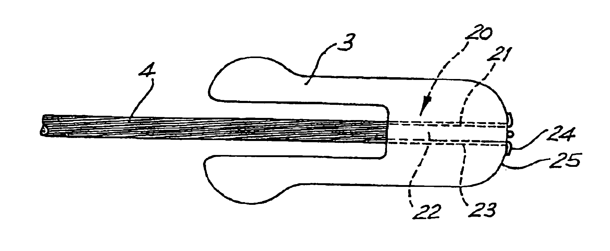
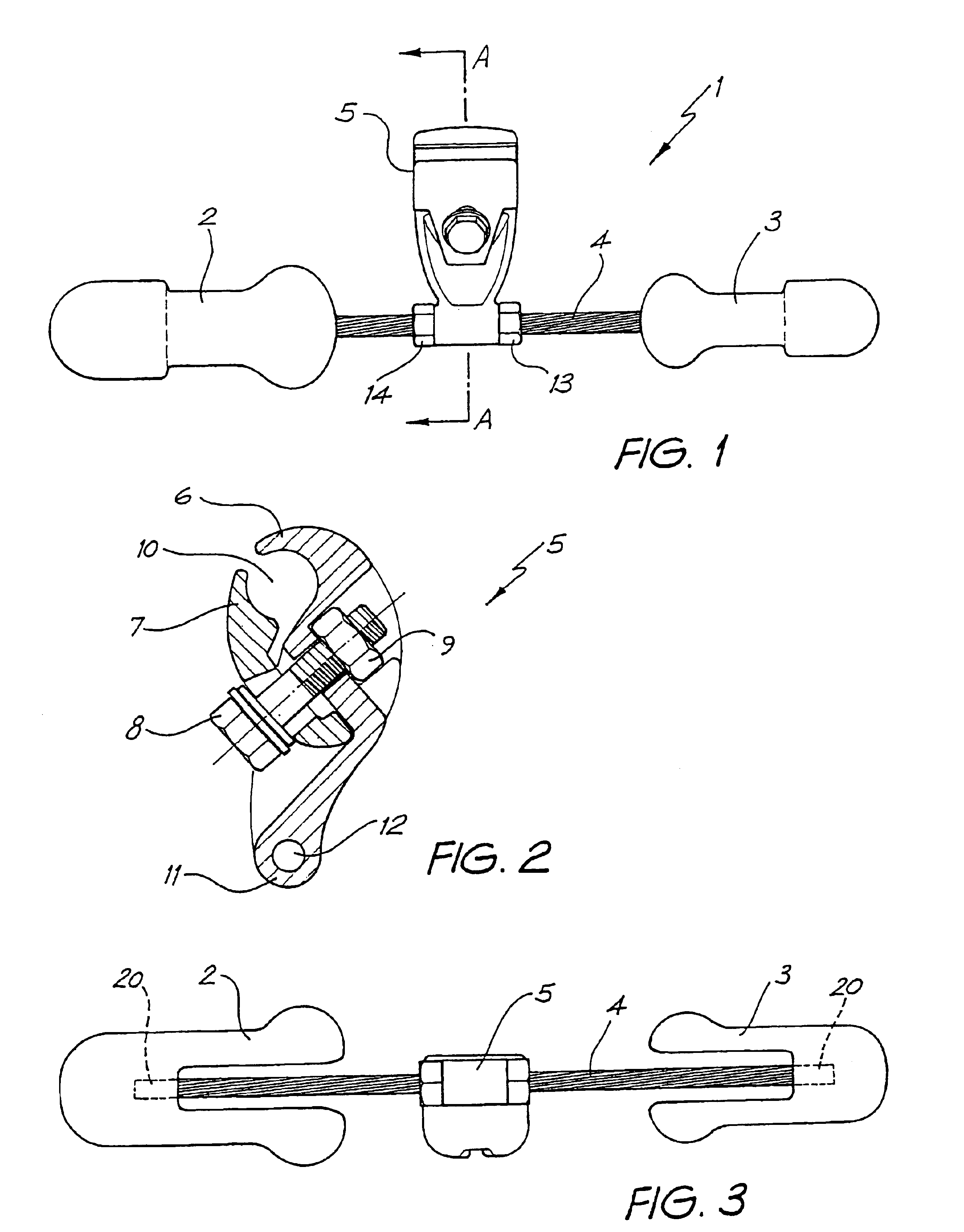
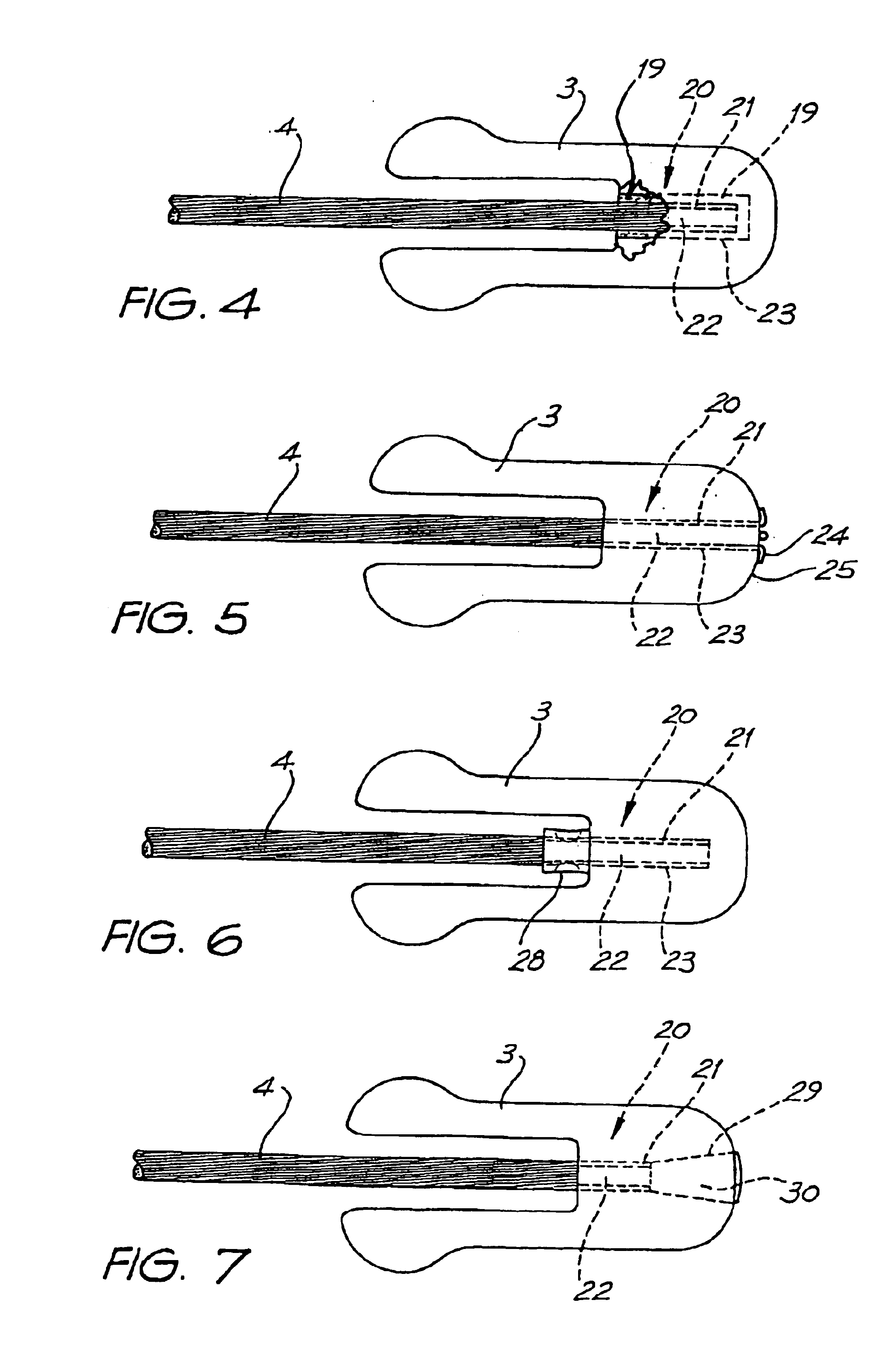
[0033]Referring to FIGS. 1 and 3, a Stockbridge vibration damper 1 is depicted. The damper comprises a pair of damping, weights 2, 3 joined by a stranded steel cable 4 known as a messenger cable. A clamp 5 is attached to the cable at a location intermediate the damping weights to provide for attachment to an overhead power transmission line.

[0034]The Stockbridge damper functions both as a reactive damper and a coulomb damper. This means that the damper sets up a reactive force in resonance with the frequency of vibration being experienced, but out of phase with it. At the same time it absorbs energy through interstrand friction of the messenger cable. This energy generates heat which is dissipated in the wind. The Stockbridge damper absorbs most of the energy in this way but a small amount of energy is reflected back into the span and a small amount transmitted through the damper to the suspension clamp.

[0035]The damping weights 2, 3 are typically formed from cast iron or zinc and d...


PUM


Abstract

This invention relates to the design and manufacture of Stockbridge type vibration dampers for overhead power transmission lines. The invention provides a Stockbridge vibration damper comprising a pair of damping weights joined by a stranded steel cable, a clamp attached to the cable at a location intermediate the weights for attachment to an overhead power transmission line. The stranded steel cable comprises two or more layers of wire, wherein at the point of connection of the damping weight to the stranded steel cable one layer of wires is attached to the weight and the remaining layer(s) of wires is / are free to move.

Description

FIELD OF THE INVENTION[0001]The present invention relates to the design and manufacture of Stockbridge type vibration dampers for overhead power transmission lines.BACKGROUND OF THE INVENTION[0002]1. Field of the Invention[0003]A Stockbridge vibration damper is a seismic device used for damping overhead power transmission lines. Stockbridge vibration dampers comprise of a pair of weights joined by a stranded steel cable (commonly known as a “messenger cable”) and a clamp attached to the cable at a location intermediate the weights for attachment to an overhead power transmission cable. The configuration of weights mounted on the ends of the messenger cable is designed to resonate at frequencies determined to be appropriate for the vibration occurring in the transmission line cable.[0004]2. Description of the Prior Art[0005]Stockbridge vibration dampers function in two ways:[0006](a) by exerting a force out of phase with the conductor vibration, and[0007](b) by dissipating the energy...

Claims


Application Information

Patent Timeline
IPC IPC(8): H02G7/00H02G7/14
CPCH02G7/14
Inventor DULHUNTY, PHILIP WELLESLEY
Owner DULHUNTY POWER AUST
Why Eureka
Try Eureka