
Welding tip for arc welding and arc welding apparatus

Inactive Publication Date: 2005-09-13
DAIDO STEEL CO LTD
View PDF7 Cites 22 Cited by
  • Summary
  • Abstract
  • Description
  • Claims
  • Application Information

AI Technical Summary

Benefits of technology

[0021]An object of the present invention is to provide a welding tip for arc welding capable of producing a stable arc and permitting a contact to have an improved durability and to provide an arc welding apparatus comprising a welding tip of this kind.
[0022]Another object of the present invention is to provide a welding tip for arc welding capable of reducing accumulation of chippings therein and an arc welding apparatus comprising such a welding tip.

Problems solved by technology

On the other hand, the increased welding current can increase a weld penetration depth in a base metal, resulting in burn-through in the thin plate welding.
However, a welding torch having an insulating guide at a distal end of a contact cannot maintain a constant contact point, i.e., a constant feeding point between the welding wire and the contact, causing unstable power supply which results in an unstable arc.
This makes the contact point unstable and hence the power supply tends to be unstable.
Further, such a variation in contact point causes local fusion of the feeding tip and the formation of an oxide layer therein, so that the contact is liable to be consumed.
Though a relatively stable arc is obtainable at an early stage of usage of the contact, the arc becomes unstable with the advance of the contact being consumed.
However, the contact 200 provided at its distal end with the insulating guide 218 entails such a drawback that the contact point relative to the wire W becomes unstable.
For a satisfactory arc welding, the welding wire portion on the distal end side with respect to the contact point must be heated constantly, with the wire extension length, i.e., the position of the contact point kept constant, however, the welding tip shown in FIG. 1 is insufficient in regard to this point.
However, such an arrangement cannot sufficiently stabilize the contact point.
As explained in the above, unstable arc is caused by instability in the contact point at which the welding wire is in contact with the feeder.
The instability of arc becomes noticeable as the contact being worn out due to friction between the contact and the welding wire.
Another problem is caused by chippings produced while the welding wire passes through the contact.
Specifically, such chippings accumulate in the wire insertion hole formed in the welding tip to hinder smooth wire supply.
In addition, gas shielding is deteriorated to permit pits and blow holes to be produced in a weldment.

Method used


Image

  • Welding tip for arc welding and arc welding apparatus
  • Welding tip for arc welding and arc welding apparatus
  • Welding tip for arc welding and arc welding apparatus

Examples


example 1

[0115]In the fabrication of a welding tip 101 shown in FIGS. 11 and 12 for consumable electrode type gas shielded arc welding, a reference hole having 1.30 mm inner diameter for a wire insertion hole 102c was formed in the contact 102, and then the contact was subject to crosswise slit-machining, whereby four slit grooves 102d were formed at the distal end of the contact to the depth of 12 mm so as to be circumferentially spaced from one another. Plate springs 105 having different strengths were mounted to contacts 102, thereby fabricating contacts having different wire withdrawal resistances F. At this time, the wire withdrawal resistance was measured by using a spring scale as a welding wire was caused to pass the contact.

[0116]Each of the resultant contacts 102 was built into a pulsed MAG welding apparatus, not shown, together with the insulating guide 103 and the guide holder 104 in a manner that the contact 102 was in contact with the insulating guide 103. Then, a durability we...

example 2

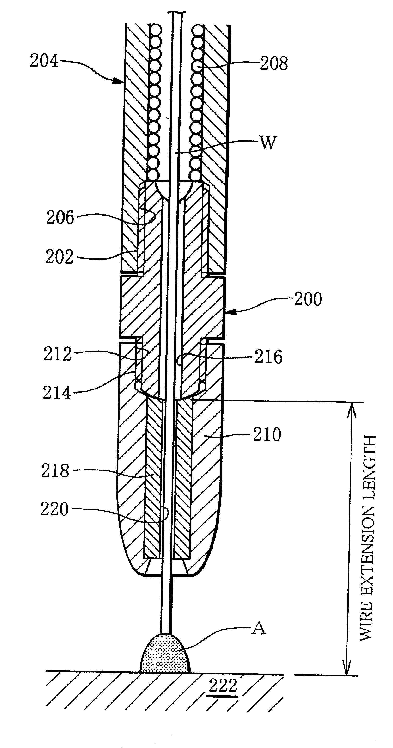
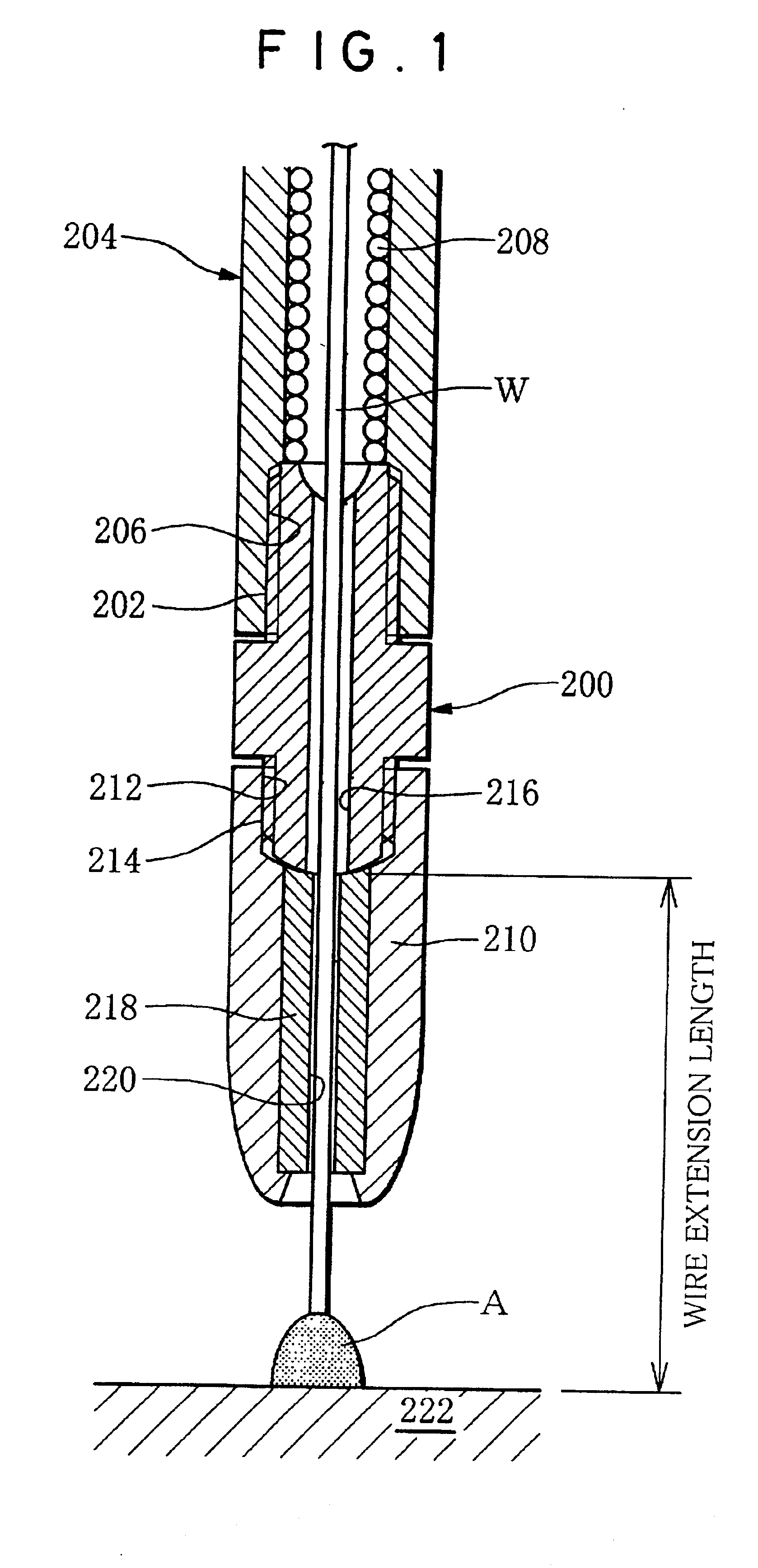
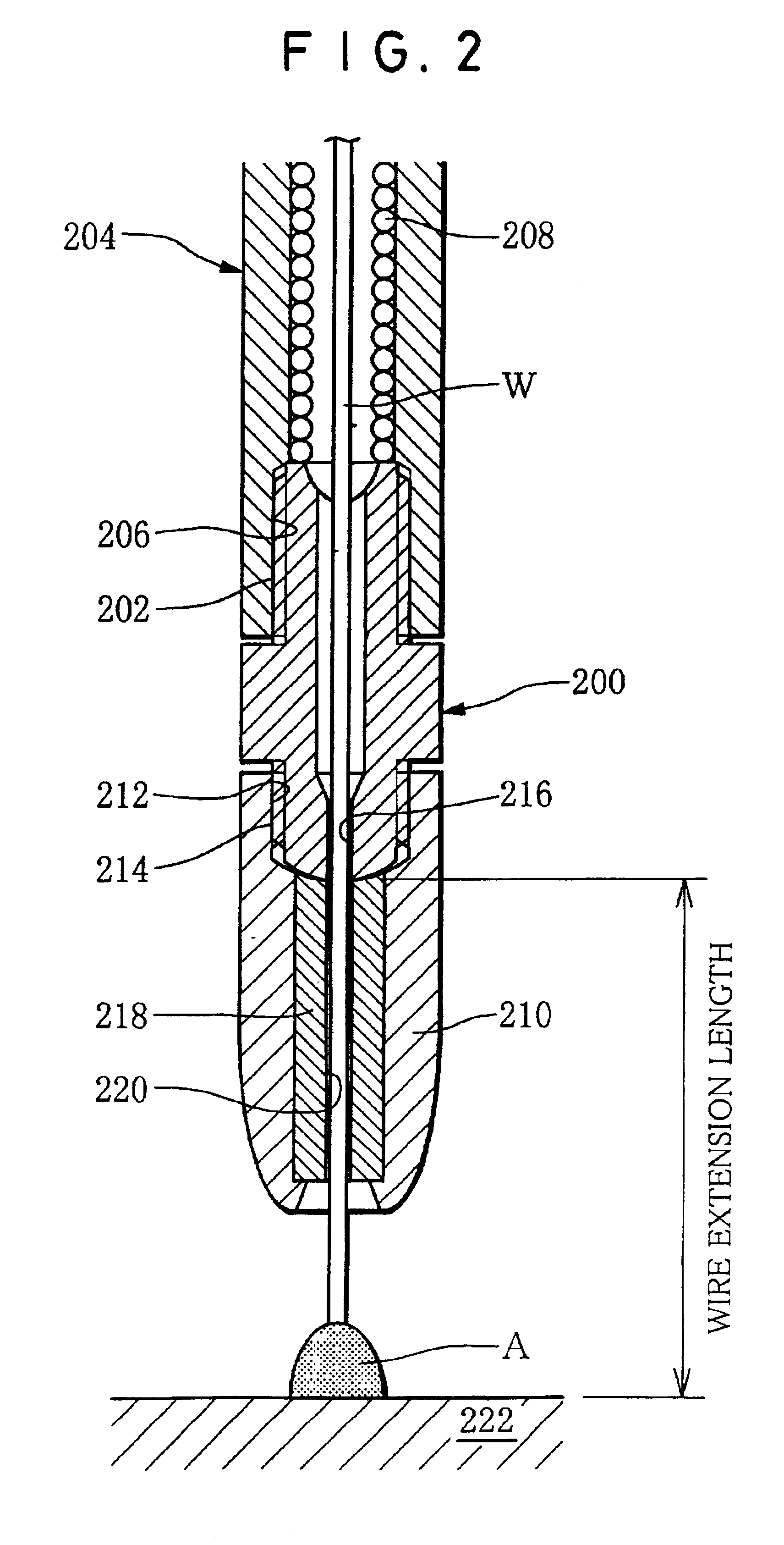
[0122]With use of the welding tip of this invention, drum-welding durability tests similar to Example 1 were performed in respect of welding wires having 0.8 mm, 1.2 mm and 1.6 mm diameters, respectively. The run-out or concentricity offset of the welding wire before start of welding, after 100 welding cycles and after 300 welding cycles were measured on the welding tip of this invention and a conventional welding tip each having no insulating guide. As for evaluation of the run-out of the welding wire, the wire extension length was intentionally lengthened up to 150 mm, and a target test or fixed-point punching test was conducted in which the welding wire was delivered toward a graph paper to form a hole therein. A measured value was divided by 15 to be converted into the run-out per wire extension length of 10 mm. The run-out equal to or less than one half of the wire diameter D (i.e., equal to or less than 0.4 mm, 0.6 mm and 0.8 mm for wire diameters of 0.8 mm, 1.2 mm and 1.6 mm,...


PUM

PropertyMeasurementUnit
Lengthaaaaaaaaaa
Lengthaaaaaaaaaa
Fractionaaaaaaaaaa

Abstract

A contact provided in a welding tip of an arc welding apparatus includes a tip body adapted to be mounted to a welding torch body and a tip end member formed integrally therewith. The tip end member is divided into two parts, i.e., first and second halves by means of a slit formed along the axis of the tip end member, and the first half having the predetermined rigidity is movable around a connection between itself and the tip body. A spring member fitted on the tip end member applies a spring force thereto, whereby the contact has improved durability.

Description

BACKGROUND OF THE INVENTION[0001]1. Technical Field[0002]The present invention relates to a welding tip for arc welding that includes a contact having an insulating guide which serves to increase a wire extension length measured from a contact point, and a metal guide which accommodates therein the insulating guide. More particularly, the present invention relates to a welding tip capable of maintaining a stable electric contact between a contact and a welding wire to stably generate arc between the welding wire and a base material, and relates to an arc welding apparatus provided with a welding tip of this kind.[0003]2. Related Art[0004]An arc welding apparatus is configured to feed a welding wire from a wire supplying apparatus toward a contact of a welding tip mounted to a welding torch and to supply welding current to the welding wire through the contact, whereby welding is performed by utilizing arc heat produced between a base material and the welding wire.[0005]A consumable e...

Claims


Application Information

Patent Timeline
IPC IPC(8): B23K9/173
CPCB23K9/173
Inventor TAKAGI, RYUUHEIUENAKA, AKIOSUZUKI, HIROAKIKAGAWA, KEIICHIROTSUKAHARA, YASUYUKI
Owner DAIDO STEEL CO LTD
Features
  • Generate Ideas
  • Intellectual Property
  • Life Sciences
  • Materials
  • Tech Scout
  • Unparalleled Data Quality
  • Higher Quality Content
  • 60% Fewer Hallucinations
Learn More