Z-slope test to optimize sample throughput

a sample throughput and z-slope technology, applied in the field of high-performance computer graphics systems, can solve the problems of complex processing, huge computational load on applications' graphics systems, and incompatibility of modern high-performance graphics systems with graphics processors with a great deal of complexity and power

Inactive Publication Date: 2005-09-13
ORACLE INT CORP
View PDF6 Cites 7 Cited by
  • Summary
  • Abstract
  • Description
  • Claims
  • Application Information

AI Technical Summary

Benefits of technology

[0013]A method with a conditional test may calculate the value or values needed for the specified test from vertex data and compare the calculated value with a specified limit. In some embodiments, a multiple storage mode may only be utilized for polygons greater than a certain size. In other embodiments, a multiple storage mode may be utilized for polygons that have an absolute Z slope less than a threshold value. In these applications, a user may utilize a high threshold value as a means to speed processing and ensure a real time display of a complex image. In some embodiments, a multiple storage method is utilized for polygons that have insubstantial differences between parameter values for neighboring sample positions within the polygon. Still other embodiments may use a conditional mode called Edge mode N. If an edge of the polygon intersects a sample bin, each sample position that is within the sample bin and within the polygon is individually rendered and stored. If an edge of the polygon does not intersect the sample bin, then the sample positions that are within the sample bin and within the polygon may be processed with a mode N method discussed above.

Problems solved by technology

These new applications place tremendous computational loads upon graphics systems.
Consequently, modern high performance graphics systems incorporate graphics processors with a great deal of complexity and power, and the color value of one pixel may be the accumulated result of many calculations involving several models and mathematical approximations.
With each new generation of graphics system, there is more image data to process, the processing is more complex, and there is less time in which to process it.

Method used


Image

  • Z-slope test to optimize sample throughput
  • Z-slope test to optimize sample throughput
  • Z-slope test to optimize sample throughput

Examples


Embodiment Construction

Computer System—FIG. 1

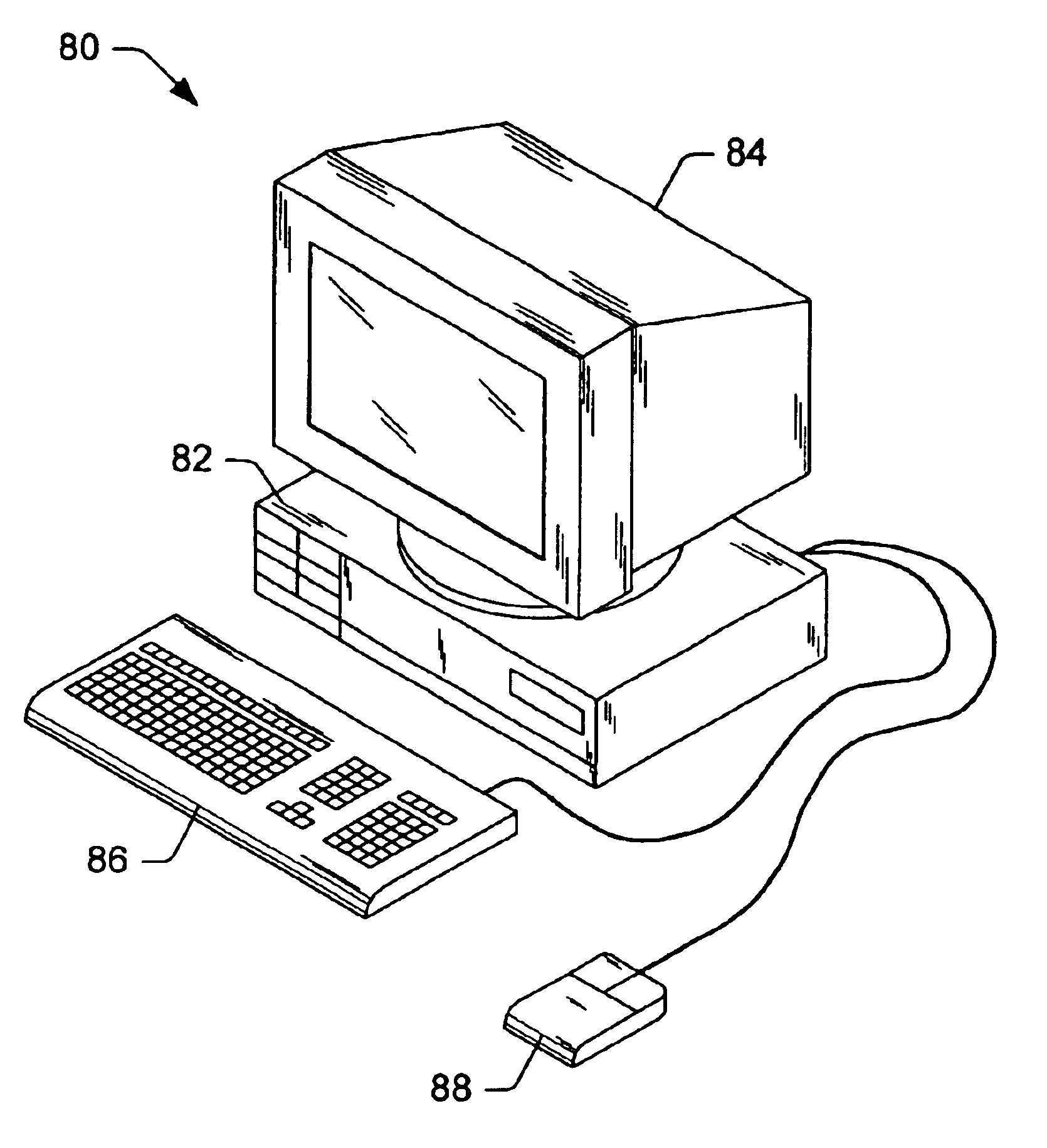
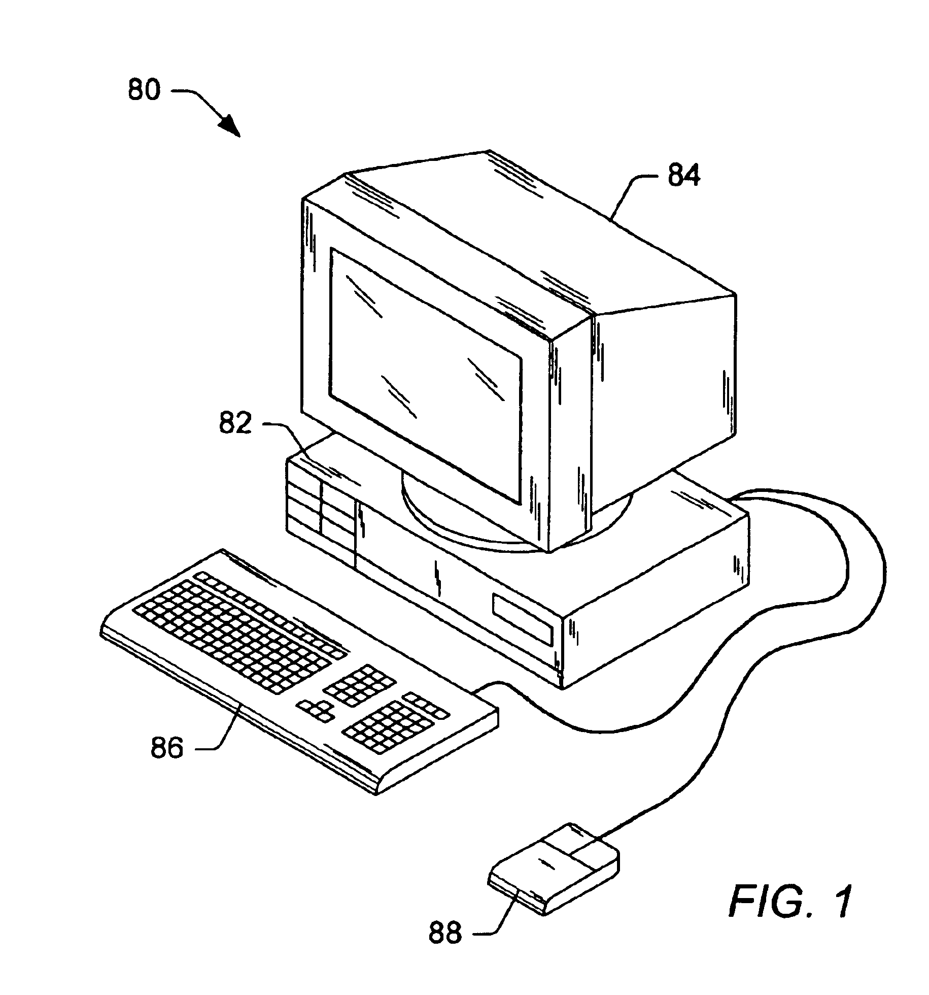
[0029]FIG. 1 illustrates one embodiment of a computer system 80 that includes a graphics system. The graphics system may be included in any of various systems such as computer systems, network PCs, Internet appliances, televisions (e.g. HDTV systems and interactive television systems), personal digital assistants (PDAs), virtual reality systems, and other devices which display 2D and / or 3D graphics, among others.

[0030]As shown, the computer system 80 includes a system unit 82 and a video monitor or display device 84 coupled to the system unit 82. The display device 84 may be any of various types of display monitors or devices (e.g., a CRT, LCD, or gas-plasma display). Various input devices may be connected to the computer system, including a keyboard 86 and / or a mouse 88, or other input device (e.g., a trackball, digitizer, tablet, six-degree of freedom input device, head tracker, eye tracker, data glove, or body sensors). Application software may be executed b...


PUM


Abstract

A system and method are disclosed for utilizing a Z slope test to select polygons that may be candidates for multiple storage methods. The method may calculate the absolute Z slope from vertex data and compare the calculated value with a specified threshold value. In some embodiments, for polygons that have an absolute Z slope less than the threshold value, parameter values may be rendered for only one sample position of multiple neighboring sample positions. The parameter values rendered for the one sample position may then be stored in multiple memory locations that correspond to the multiple neighboring sample positions. In some embodiments, storing parameter values in multiple memory locations may be achieved in a single write transaction. In some embodiments, utilization of the Z slope test method may be subject to user input and in other embodiments may be a dynamic decision controlled by the graphics system.

Description

BACKGROUND OF THE INVENTION[0001]1. Field of the Invention[0002]This invention relates generally to the field of computer graphics and, more particularly, to high performance computer graphics systems.[0003]2. Description of the Related Art[0004]Early graphics systems were limited to two-dimensional (2D) graphics, were configured to compute a gray scale value for each pixel displayed, and acted as simple translators or interfaces to a display device. Modem high performance graphics systems, however, may support three-dimensional (3D) graphics with one or more special effects such as anti-aliasing, texturing, shading, fogging, alpha-blending, and specular highlighting. 3D graphics data may be several orders of magnitude larger than comparable 2D graphics data. 3D graphics data may include a set of information components for each vertex of the geometric primitives used to model the objects to be imaged.[0005]In recent years, demand for high performance graphics systems that can render...

Claims


Application Information

Patent Timeline
Patent Type & Authority Patents(United States)
IPC IPC(8): G06T15/00
CPCG06T15/005G06T2200/28
Inventor PASCUAL, MARK E.LAVELLE, MICHAEL G.DEERING, MICHAEL F.RAMANI, NANDINI
Owner ORACLE INT CORP
Why Eureka
Try Eureka