Head support mechanism, information recording/reproducing apparatus, and method of manufacturing head support mechanism

Inactive Publication Date: 2005-09-13
PANASONIC CORP
View PDF23 Cites 21 Cited by
  • Summary
  • Abstract
  • Description
  • Claims
  • Application Information

AI Technical Summary

Benefits of technology

[0031]The bent portion may be bent in a direction which is substantially perpendicular to the disk surface

Problems solved by technology

Therefore, the piezoelectric ceramics need to be expanded or contracted (deformed) against a substantial inplane rigidity, which disadvantageously requires a considerably high applied driving voltage (e.g., 20 V), similar to the above-described conventional example disclosed in Japanese Laid-open Publication No. 9-73746.
Since this two-stage controlled actuator is of a type which is mounted on the back face of a slider, a thickness of the magnetic disk apparatus in a height direction there

Method used


Image

  • Head support mechanism, information recording/reproducing apparatus, and method of manufacturing head support mechanism
  • Head support mechanism, information recording/reproducing apparatus, and method of manufacturing head support mechanism
  • Head support mechanism, information recording/reproducing apparatus, and method of manufacturing head support mechanism

Examples


embodiment 1

(Embodiment 1)

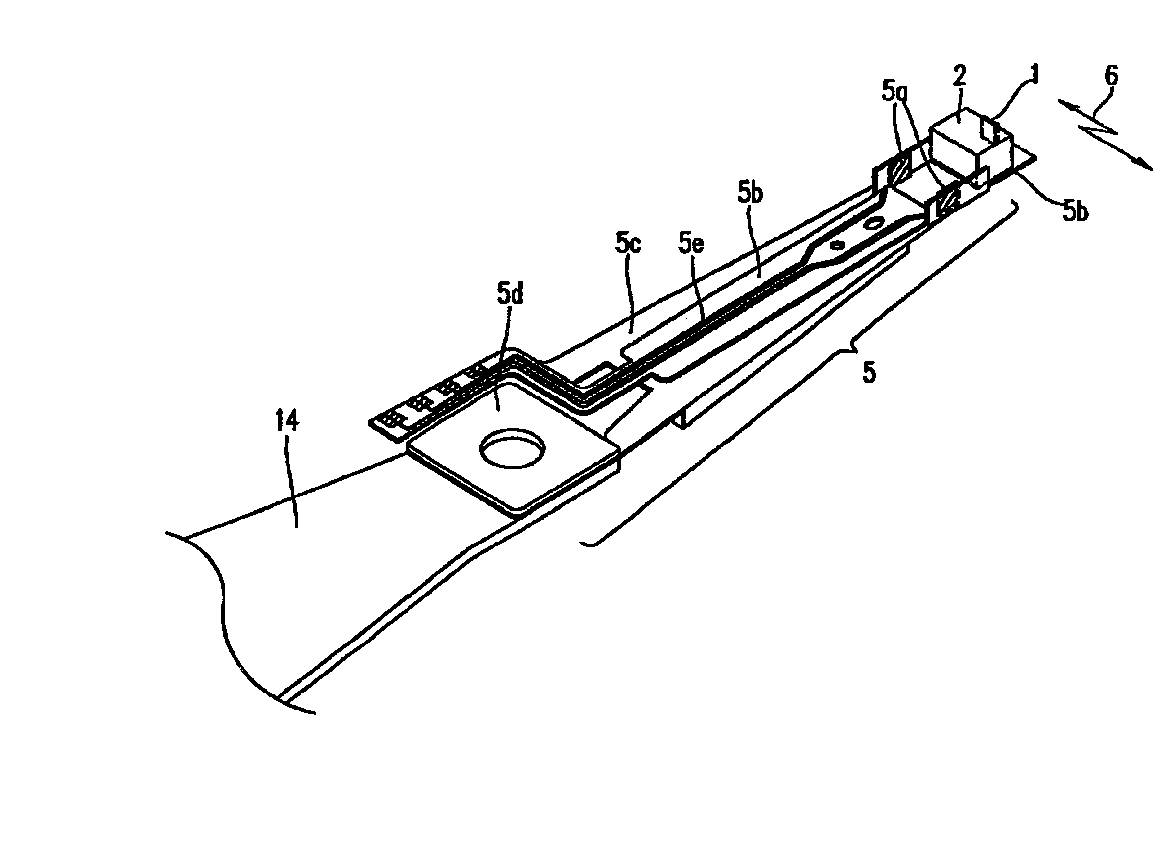
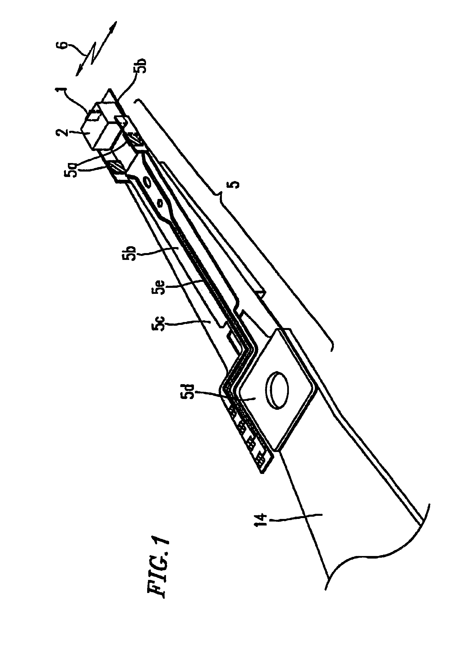
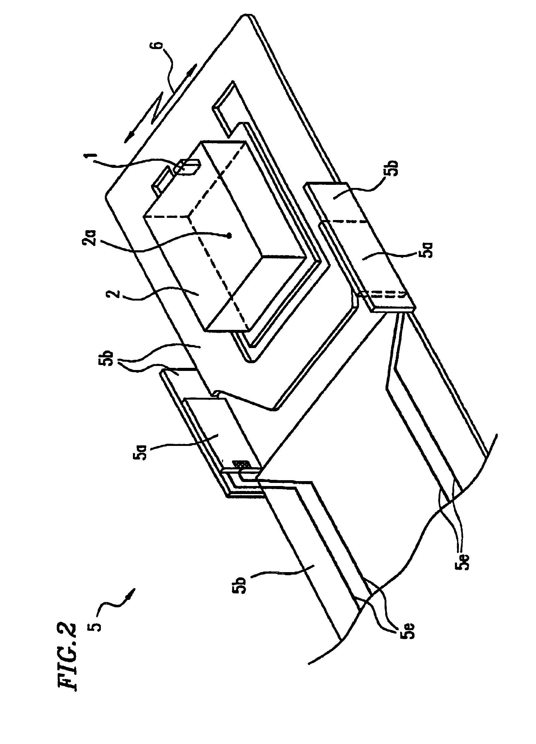
[0151]FIG. 1 is a perspective view showing a head support mechanism according to Embodiment 1 of the present invention. FIG. 2 is a partially-enlarged perspective view showing the head support mechanism according to Embodiment 1 of the present invention.

[0152]Both of these figures are perspective views showing the head support mechanism as viewed from a disk surface.

[0153]FIG. 3 is a perspective view showing a magnetic disk apparatus incorporating the head support mechanism according to the present invention. FIG. 4 is a vertical cross-sectional view showing a main part of the magnetic disk apparatus incorporating the head support mechanism according to the present invention.

[0154]In FIGS. 1 to 4, reference numeral 1 denotes a head for recording and reproducing information; 2 denotes a slider carrying the head; 3 denotes a disk which is rotated by a motor and on which information is recorded or reproduced; 4 denotes a main driving means for causing the head to track; 4...

embodiment 2

(Embodiment 2)

[0181]FIG. 8 is a partially-enlarged perspective view of a head support mechanism 205 according to Embodiment 2 of the present invention. Most of component members and the reference numerals thereof are the same as those described in Embodiment 1 above, and the detailed description of the same contents will not be repeated. A flexure 205b in the head support mechanism according to Embodiment 2 features a structure having three parallel thin plates, as opposed to the structure of Embodiment 1 in which two parallel thin plate springs are present.

[0182]On two of the three parallel thin plate springs, micro-movement driving sub-means 5a for the head is provided, similarly to Embodiment 1. However, on the other thin plate spring, recording / reproduction signal wiring 5f for loading recording / reproduction signals in the head 1 to the exterior is provided. By thus dedicating some of a plurality of thin plate springs to signal wiring only, it is possible to prevent deterioratio...

embodiment 3

(Embodiment 3)

[0184]FIG. 9 is a partially-enlarged perspective view of a head support mechanism 305 according to Embodiment 3 of the present invention. Most of component members and the reference numerals thereof are the same as those described in Embodiments 1 and 2 above, and the detailed description of the same contents will not be repeated. Driving sub-means 5a for the head provided on a flexure 305b in the head support mechanism according to Embodiment 3 rotates around a z axis of a slider 2 that extends in a height direction from the disk, in the neighborhood of the center of gravity 2a of the slider 2.

[0185]In FIG. 9, the rotation axis Z which is in a position at a distance d from the center of gravity 2a of the slider, as well as a rotation direction 7 around this, is shown. As the slider rotates around the z axis, a head 1 provided on a rear end face of the slider undergoes micro-movement along tracking directions 6. In this method, slight changes in the azimuth angle of th...


PUM


Abstract

A head support mechanism includes a head and a slider for carrying the head, the head being caused to track by main driver, wherein the head support mechanism further includes sub-driving device including a thin film and causing the head to have a micro-movement; and the sub-driving device causes the head to have a micro-movement by utilizing flexural deformation of the thin film.

Description

[0001]This application is a U.S. National Phase Application of PCT International Application PCT / JP99 / 05061.TECHNICAL FIELD[0002]The present invention relates to a head support mechanism, an information recording / reproducing apparatus incorporating the same, and a method of manufacturing the head support mechanism. More particularly, the present invention relates to a head support mechanism including a micro-movement driving means, and an information recording / reproducing apparatus incorporating the same, and a method of manufacturing the head support mechanism.BACKGROUND ART[0003]Magnetic disk apparatuses as information recording / reproducing apparatuses have been used as chief external memory devices for computers because of their large capacity, high transfer rates, and high-speed random access capabilities. In particular, there is a marked recent trend toward larger capacity magnetic disk apparatuses, the density being increased at an annual rate of 60%. Correspondingly, the size...

Claims


Application Information

Patent Timeline
IPC IPC(8): G11B5/55G11B5/48
CPCG11B5/484G11B5/4853G11B5/5552G11B5/3103G11B5/3163G11B2220/2508
Inventor YOKOYAMA, KAZUOYAMAMOTO, SHINICHIIRIE, YOUSUKEKUWAJIMA, HIDEKISAKAMOTO, KENICHIMATSUOKA, KAORUKANNO, ISAKUFUJII, SATORU
Owner PANASONIC CORP
Why Eureka
Try Eureka