Eureka AIR delivers breakthrough ideas for toughest innovation challenges, trusted by R&D personnel around the world.

Message format and flow control for replacement of the packet control driver/packet interface dual port RAM communication

a technology of message format and flow control, applied in the field of packet control driver and packet interface, can solve the problems of increasing system cost and limiting system versatility, and achieve the effect of removing hardware dependency

Inactive Publication Date: 2005-09-13
AVAYA INC
View PDF2 Cites 17 Cited by
  • Summary
  • Abstract
  • Description
  • Claims
  • Application Information

AI Technical Summary

Benefits of technology

[0005]These and other needs are addressed by the architectures and methods of the present invention. Generally, the present invention provides a new message set and / or flow control mechanism and a networked architecture for managing telecommunication devices such as telephones, voicemail, e-mail, fax, and other communication end points. The new message set and flow control mechanism maps to existing (conventional) dual port RAM queues, tables, interrupts, and other memory locations, thus removing hardware dependency on the packet control driver / packet interface communications and allowing control of LAPD links to be remoted.
[0010]In this configuration, queues, tables, interrupts, or other variables in the dual port RAM of a conventional system are mapped to a corresponding message type and index. Both the controller, e.g., packet control driver, and interface, e.g., packet interface, maintain a copy of all of the queues, tables, interrupts, and other variables that are normally stored in the dual port RAM in a conventional system. When the variables are written to the memory accessed by a packet control driver or to the memory of a packet interface, a message is sent to the other of the packet control driver and packet interface with the appropriate type and index to indicate what has changed. If a data packet needs to be sent by the packet control driver or packet interface (which was previously done by a queue in the dual port RAM), a message is created with a type and index corresponding to the queue that the packet would normally been placed in (in a conventional system) and is then sent to the other of the packet control driver and packet interface. Upon receipt, the message is written into a queue accessed by the other of the packet control driver or packet interface. This methodology effectively moves the packet control driver / packet interface communications out of dual port RAM and, by sending the message set over a serial stream, packet control driver / packet interface communication dependency on hardware is removed and simplified, thereby reducing costs.
[0018]The architecture can have advantages in addition to those set forth above. In one configuration, the interface means such as a packet interface is always subservient to the controller such as a packet control driver and will accept whatever parameters the controlling means or controller sends the interface means. This structure has benefits including a faster setup time, greater control of the flow control mechanism by the controlling means, thereby permitting faster changes in buffer allocation strategies, and reductions in the workload of the interface means through removal from the interface means of responsibility for buffer management. In another configuration, the controlling means or controller is located at one geographic location and each of the telecommunication subsystems are at a plurality of other geographic locations remote from the location of the controller and / or the locations of the other subsystems.
[0029](b) at least one of incrementing or decrementing a counter in response to the message. As noted, the counter is related to the capacity of a memory accessed by a telecommunications component. The counter can be related to the grouping of links and / or an individual link. In one configuration, the links are grouped by link type, thus allowing buffer allocation and flow control parameters to be controlled on a per link type basis. This design can match the packet control driver / packet interface link control strategies of many conventional systems and allows flow control parameters to be distributed faster and more effectively.

Problems solved by technology

The separation distance limitation restricts the versatility of the system.
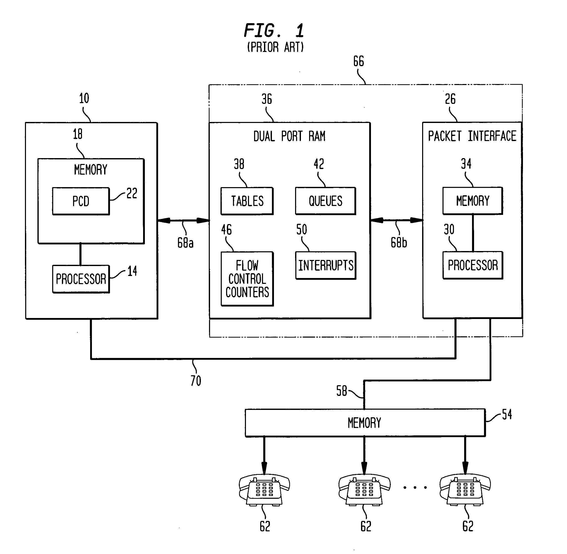
As can be seen from the illustration, a large number of boards are employed to increase contact center capacity which increases the cost of the system, and all port network messages are routed inefficiently through a single packet bus 58 of a selected port network.

Method used


Image

  • Message format and flow control for replacement of the packet control driver/packet interface dual port RAM communication
  • Message format and flow control for replacement of the packet control driver/packet interface dual port RAM communication
  • Message format and flow control for replacement of the packet control driver/packet interface dual port RAM communication

Examples


Embodiment Construction

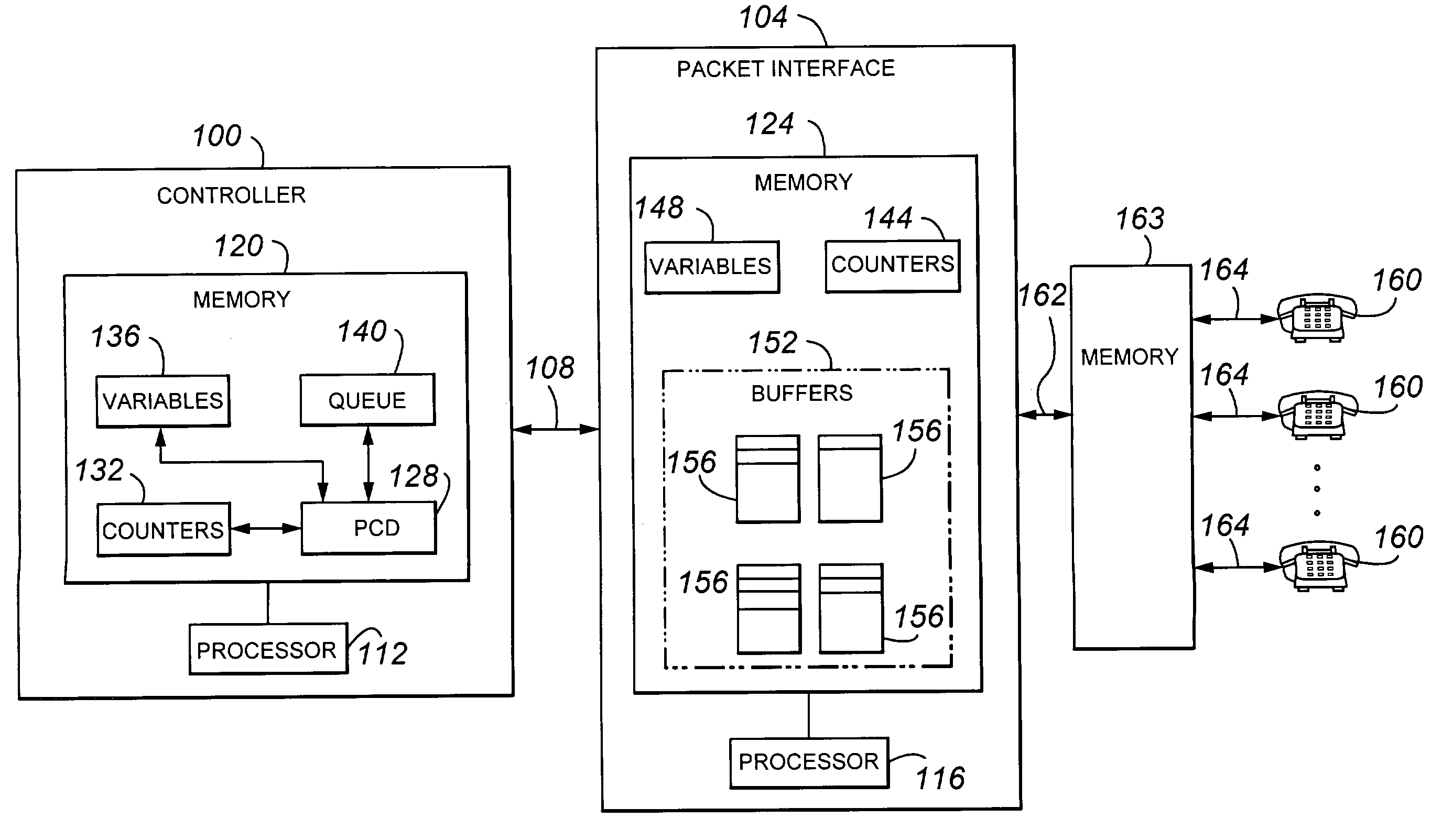
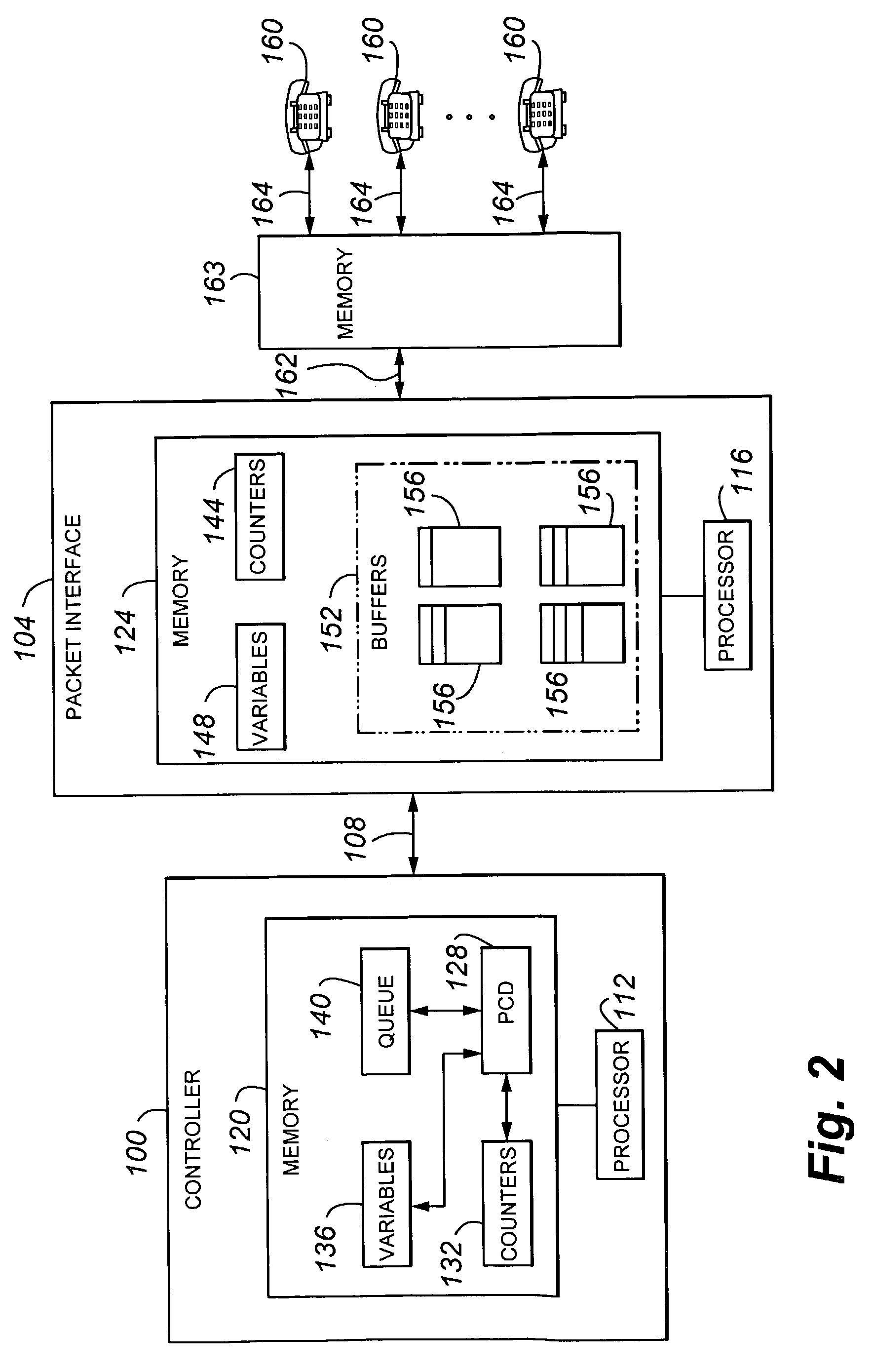
[0049]Referring to FIG. 2, a contact or call switching architecture according to an embodiment of the present invention is depicted. The architecture includes a controller 100 connected to a packet interface 104 via network line 108. The controller 100 and packet interface 104 respectively include a processor 112, 116 and memory 120, 124. Controller memory 120 includes a packet control driver 128, various counters 132 (which provide information on the operation of the packet interface), queue(s) 140 and other variables 136. Packet interface memory 124 includes counters 144, queues in buffers 152 and other variables 148. The queues 156 typically follow a first-in-first-out standard. The packet interface 104 is in turn connected memory (ISDN) board(s) 163 via a packet bus 162 and the memory (ISDN) board(s)163 are in turn connected to telephones 160 via LAPD links 164. The packet interface 104 can be further connected to a primary rate interface (PRI) trunk (not shown) and one or more ...


PUM


Abstract

The architecture of the present invention provides a new message set and / or flow control mechanism and a networked architecture for managing telecommunication devices such as telephones, fax, voicemail, e-mail, and other communication endpoints. The new message set and flow control mechanism maps to existing (conventional) dual port RAM queues, tables, interrupts, and other memory locations, thus removing hardware dependency on the packet control driver / packet interface communications and allowing control of LAPD links to be remoted.

Description

FIELD OF THE INVENTION[0001]The present invention relates generally to telecommunication systems and specifically to a system including a packet control driver and packet interface and its method of operation.BACKGROUND OF THE INVENTION[0002]Telecommunication contractor switching centers, such as used in a private branch or automatic exchange, use a variety of architectures to handle contacts. In one configuration depicted in FIG. 1 and sold by Lucent Technologies, Inc., under the tradename Definity™, the switching center includes a controlling architecture 10 that includes a processor 14, a memory 18, and a packet control driver 22; a packet interface 26 that includes a processor 30 and memory 34; dual port RAM 36 that includes tables 38 (e.g., link address table, link control table, link data table, link status table, etc.), queues 42, and variables such as counters 46 and interrupts 50; one or more memory (ISDN) boards 54 (which are attached to the packet interface by way of pack...

Claims


Application Information

Patent Timeline
IPC IPC(8): H04L12/26
CPCH04L47/26H04L47/30H04L47/41Y02B60/33Y02D30/50
Inventor DUNCAN, CHARLES R.
Owner AVAYA INC
Why Eureka
Eureka Blog
Learn More