10 Gigabit ethernet mappings for a common LAN/WAN PMD interface with a simple universal physical medium dependent interface

Active Publication Date: 2005-09-13
CIENA
View PDF18 Cites 71 Cited by
  • Summary
  • Abstract
  • Description
  • Claims
  • Application Information

AI Technical Summary

Benefits of technology

[0018]An advantage of the present invention is that a common physical medium dependent (PMD) interface can be used, independ

Problems solved by technology

Despite its versatility, the technique of Canadian Patent Application Serial No. 2,273,522 is unattractive for use in LAN configurations, because HS Ethernet LANs commonly provide a data rate of 10 Gb/s.
As a result, implementation of this technique in LAN configurations would have the effect of degrading

Method used


Image

  • 10 Gigabit ethernet mappings for a common LAN/WAN PMD interface with a simple universal physical medium dependent interface
  • 10 Gigabit ethernet mappings for a common LAN/WAN PMD interface with a simple universal physical medium dependent interface
  • 10 Gigabit ethernet mappings for a common LAN/WAN PMD interface with a simple universal physical medium dependent interface

Examples


Embodiment Construction

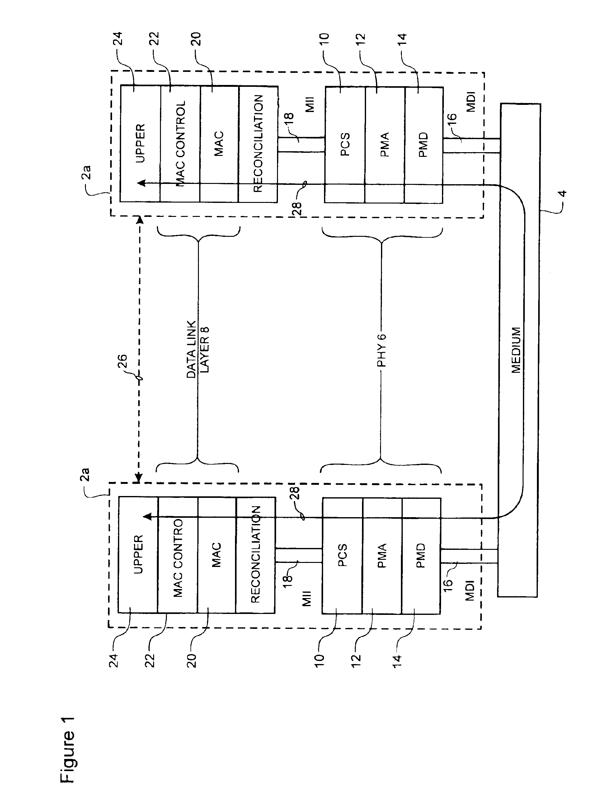
[0029]FIG. 1 illustrates a communications network including a pair of nodes 2a, 2b (such as personal computers and LAN servers) connected for data communications through a network medium 4. The nodes 2a, 2b are represented by the standard Ethernet reference model which utilizes a multi-layer architecture made up of a physical layer (PHY) 6 and a data link layer 8. The PHY 6 is divided into three sub-layers, namely a physical coding sub-layer (PCS) 10, a physical medium attachment (PMA) sub-layer 12, and a physical medium dependent (PMD) sub-layer 14. A Medium Dependent Interface (MDI) 16 couples the PHY 6 to the medium 4 (i.e. the network fabric). A Medium Independent Interface (MII) 18 couples the PHY 6 to the data link layer 8, which is composed of Media Access Control (MAC) 20 and (optionally) MAC control 22 sub-layers. Upper layers 24 containing, for example, end-user software applications (not shown) are coupled to the data link layer 8 to facilitate communications between each...


PUM


Abstract

An Ethernet mapping enables high speed Ethernet data streams having a data rate of 10 Gb/s to be transported across a synchronous packet switched network fabric having a standard SONET OC-192 line rate of 9.953280 Gbaud. The 10 Gb/s Ethernet data stream is compressed by removing interframe gaps between successive MAC frames to produce a compressed data stream, which is then mapped to a synchronous container. The synchronous container is then launched across the synchronous packet switched network fabric at a standard SONET OC-192 line rate of 9.953280 Gbaud. The synchronous container is preferably provided as a stripped STS-192c frame having only A1 and A2 octets of the Transport Overhead (TOH). The compressed data stream is mapped directly to the synchronous container, starting at the first octet following the A1 and A2 octets, without first being inserted into a conventional STS-192c SPE, so that most of the space normally used for TOH and Path overhead (POH) within a conventional STS-192c frame is freed-up for carrying the compressed data stream. At a receiving interface, the compressed data stream is extracted from received synchronous containers and decompressed, by insertion of interframe gaps between successive MAC frames, to generate a recovered 10 Gb/s Ethernet data stream. The starting bit of each successive MAC frame can be identified by examination of the length field of the immediately previous MAC frame.

Description

CROSS-REFERENCE TO RELATED APPLICATIONS[0001]This application is based on U.S. Provisional Application Ser. No. 60 / 181,549, filed Feb. 10, 2000.MICROFICHE APPENDIX[0002]Not Applicable.TECHNICAL FIELD[0003]The present invention relates to high-speed data communications networks, and in particular to a method and apparatus for interfacing adjacent high-speed data communications networks.BACKGROUND OF THE INVENTION[0004]Applicant's co-pending Canadian Patent Application Serial No. 2,273,522 proposes a technique of mapping high speed (HS) Ethernet frames (e.g. originating in a local area network [LAN] using a fiber distributed data interface [FDDI] physical layer) into a synchronous container (e.g. thin synchronous optical network [SONET] STS-192C or synchronous digital hierarchy [SDH] VC-4-64C frames) for transport across a synchronous packet switched network fabric at a standard OC-192 line rate of 9.95328 Gbaud, to achieve a data rate of 9.5864 Gb / s. This data rate is obtained indepe...

Claims


Application Information

Patent Timeline
IPC IPC(8): H04J3/16H04L12/46H04Q11/04
CPCH04J3/1617H04L12/4604H04J2203/0085
Inventor BOTTORFF, PAUL A.FIGUEIRA, NORIVAL R.MARTIN, DAVID W.ARMSTRONG, TIMOTHY J.RAAHEMI, BIJAN
Owner CIENA
Why Eureka
Try Eureka