Compact ultra fast laser

a laser and ultra-fast technology, applied in the field of compact solid-state lasers, can solve the problems of increasing the complexity of the system, limiting the number of laser materials suitable for femtosecond generation, and complicated femtosecond lasers, etc., and achieve the effect of reasonable gain

Inactive Publication Date: 2005-09-13
HIGH Q LASER
View PDF10 Cites 16 Cited by
  • Summary
  • Abstract
  • Description
  • Claims
  • Application Information

AI Technical Summary

Benefits of technology

[0005]The invention relates to compact solid state lasers. The laser medium is positioned at or close to one end of the laser cavity and pumped by at least one pump source or laser diode. The pumping can be done by one or two laser diodes including imaging optics of compact size (10 cm or less), respectively, due to the arrangement of the cavity end and pumping optics, and is suitable for achieving reasonable gain even from low-gain laser materials. For femtosecond operation, the laser resonator is laid out such that both a semiconductor saturable absorber mirror and a prism pair are located toward the other end of the cavity, and the laser mode on the SESAM and the prism sequence length fulfill the requirements that have to be met for stable femtosecond generation. It is another object of the invention to provide a semiconductor saturable absorber mirror (SESAM) having a structure which comprises a plurality of alternating gallium arsenide (GaAs) and aluminum arsenide (AlA

Problems solved by technology

Femtosecond lasers are usually more complicated than other lasers emitting continuous-wave, Q-switched, or picosecond radiation.
One reason for this is that femtosecond generation requires laser materials with a spectrally broad emission band, in comparison for example to the well-known laser material Nd:YAG, leaving a limited number of laser materials suitable for femtosecond generation.
Additionally, femtosecond lasers need some group velocity dispersion compensation, which usually requires additional intra cavity elements, such as a prism pair, thereby adding complexity to the system.
These laser systems, howeve

Method used


Image

  • Compact ultra fast laser
  • Compact ultra fast laser
  • Compact ultra fast laser

Examples


Embodiment Construction

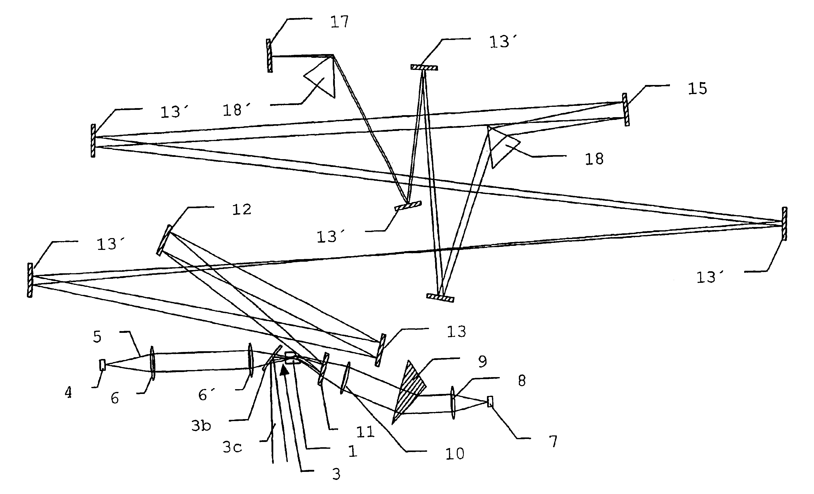
[0015]The general setup of a compact, ultra-fast laser according to a preferred embodiment of the invention shall be described with reference to FIG. 1. The gain section of the laser setup comprises a laser gain medium 1 which is located in the vicinity of a first end of a laser cavity (see laser cavity mode axis 2). The laser gain medium 1 can even be the laser cavity end itself if one side 3 of the laser material is coated for reflectivity at the laser wavelength. A flat-Brewster-cut laser medium may be used, where the flat side is coated for reflectivity at the laser wavelength and for high transmission at the wavelength of the pump laser diode 4 used in the setup. The laser diode beam is preferably collimated in the (vertical) fast-divergent axis by means of a cylindrical micro lens attached close to the laser diode 4 so that the pump beam 5 diverges at a reduced vertical divergence angle. The pump laser diode 4 can be for example a 100 micron wide laser diode emitting at a powe...


PUM


Abstract

The solid state laser comprises a laser gain medium (1), pumping means for pumping the laser gain medium, and a laser cavity having a first end (3) and a second end (17), wherein the laser gain medium is at, or in the vicinity of, said first end (3) of said cavity. A semiconductor saturable absorber mirror (SESAM) can be placed at the second end (17) of the cavity. The laser gain medium can comprise at least one face for receiving pumping energy from the pumping means, the face being made reflective at a laser frequency of the laser, so that it can form the first end of the laser cavity. The resulting setup used for generating femtosecond laser pulses.

Description

[0001]This application is the U.S. National Phase of International Application No. PCT / EP02 / 00713, which is turn is a continuation-in-part of U.S. patent application Ser. No. 09 / 768,167, filed Jan. 24, 2001, now abandonded, which in turn is a continuation-in-part of U.S. patent application Ser. No. 09 / 489,964, filed Jan. 24, 2000, now abandonded which in turn claims the benefit of U.S. Provisional Patent Application No. 60 / 146,472, filed Jul. 30, 1999.FIELD OF THE INVENTION[0002]This invention relates to compact solid state lasers.BACKGROUND OF THE INVENTION[0003]Femtosecond lasers are usually more complicated than other lasers emitting continuous-wave, Q-switched, or picosecond radiation. One reason for this is that femtosecond generation requires laser materials with a spectrally broad emission band, in comparison for example to the well-known laser material Nd:YAG, leaving a limited number of laser materials suitable for femtosecond generation. Additionally, femtosecond lasers ne...

Claims


Application Information

Patent Timeline
IPC IPC(8): H01S3/091H01S3/092H01S3/0915H01S3/00H01S3/081H01S3/0941H01S3/098
CPCH01S3/09415H01S3/005H01S3/0811H01S3/0813H01S3/1118
Inventor BUNTING, UDOKOPF, DANIEL
Owner HIGH Q LASER
Why Eureka
Try Eureka