Method of producing an integral resonator sensor and case

a resonator sensor and integrated technology, applied in the manufacture of electrical instruments, magnets, fixed capacitors, etc., can solve the problems of large internal volume for mounting additional sensors, etc., and achieve large internal volume, increased sensing capability, and substantial top and bottom surface areas

Inactive Publication Date: 2005-09-20
CALIFORNIA INST OF TECH +1
View PDF23 Cites 86 Cited by
  • Summary
  • Abstract
  • Description
  • Claims
  • Application Information

AI Technical Summary

Benefits of technology

[0027]Embodiments of the present invention provide a planar resonator supported on a central rigid stem and with substantially increased sensing capability by utilizing a short solid cylindrical resonator or disc having a substantial useable internal resonator volume, allowing the incorporation of significantly more sensing for the measurement of desirable resonator internal motion. This use of a planar element, such as a disc, rather than a shell or ring results in substantial top and bottom surface areas and a large internal volume for mounting additional sensors. A disc provides the same favorable modes for Coriolis sensing as a cylindrical or hemispherical shell.
[0029]In one embodiment of the invention, multiple concentric alternating segments or slots can be cut or etched through the disc, reducing the in-plane stiffness of the resonator. In addition, the segmented or slotted disc also obtains an increased area available for capacitive sensing. The advantages of this structure include permitting larger deflections with increased sensitivity. Alternatively, in-plane strain gauges can be placed on the top and bottom surfaces of a solid disc to provide a constant sensing area, regardless of the disc thickness. However, this approach will produce a resonator with an increased in-plane stiffness when compared with the segmented or slotted approach.

Problems solved by technology

This use of a planar element, such as a disc, rather than a shell or ring results in substantial top and bottom surface areas and a large internal volume for mounting additional sensors.

Method used


Image

  • Method of producing an integral resonator sensor and case
  • Method of producing an integral resonator sensor and case
  • Method of producing an integral resonator sensor and case

Examples


Embodiment Construction

[0054]In the following description of the preferred embodiment, reference is made to the accompanying drawings which form a part hereof, and in which is shown by way of illustration a specific embodiment in which the invention may be practiced. It is to be understood that other embodiments may be utilized and structural changes may be made without departing from the scope of the present invention.

1.0 Overview

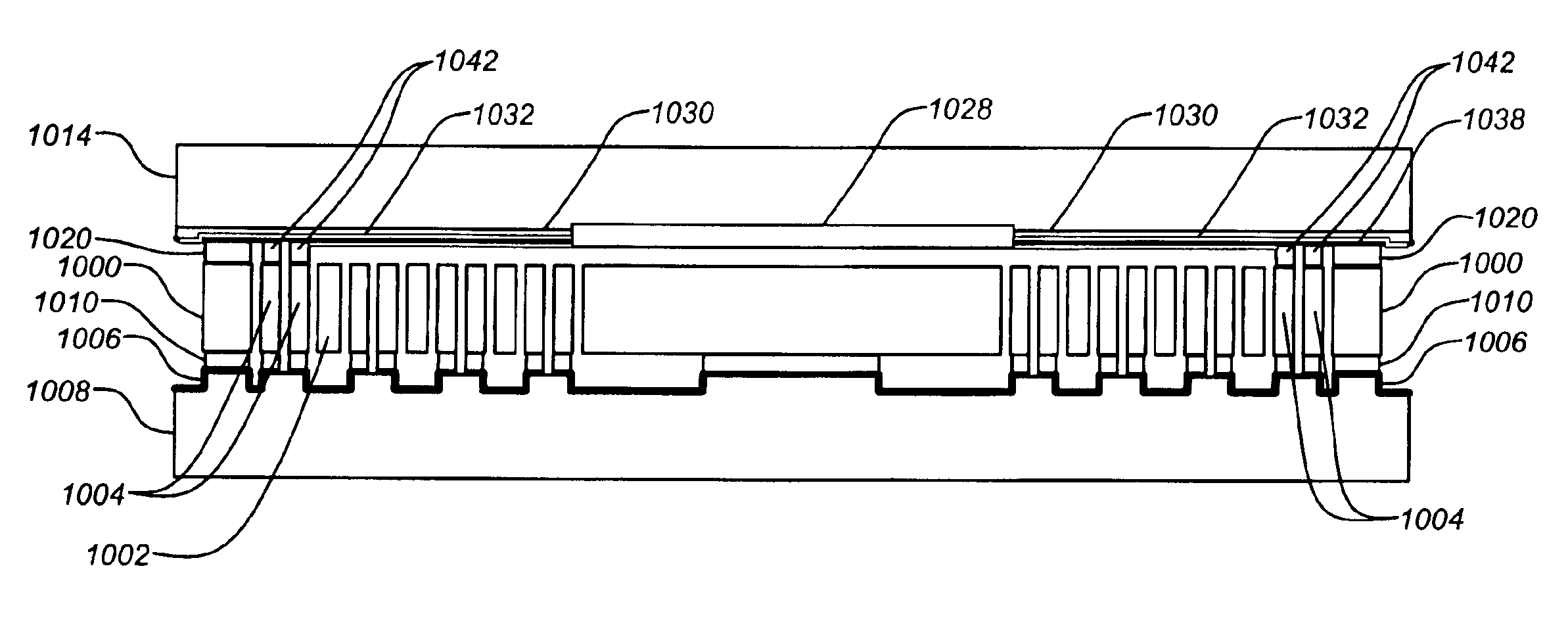
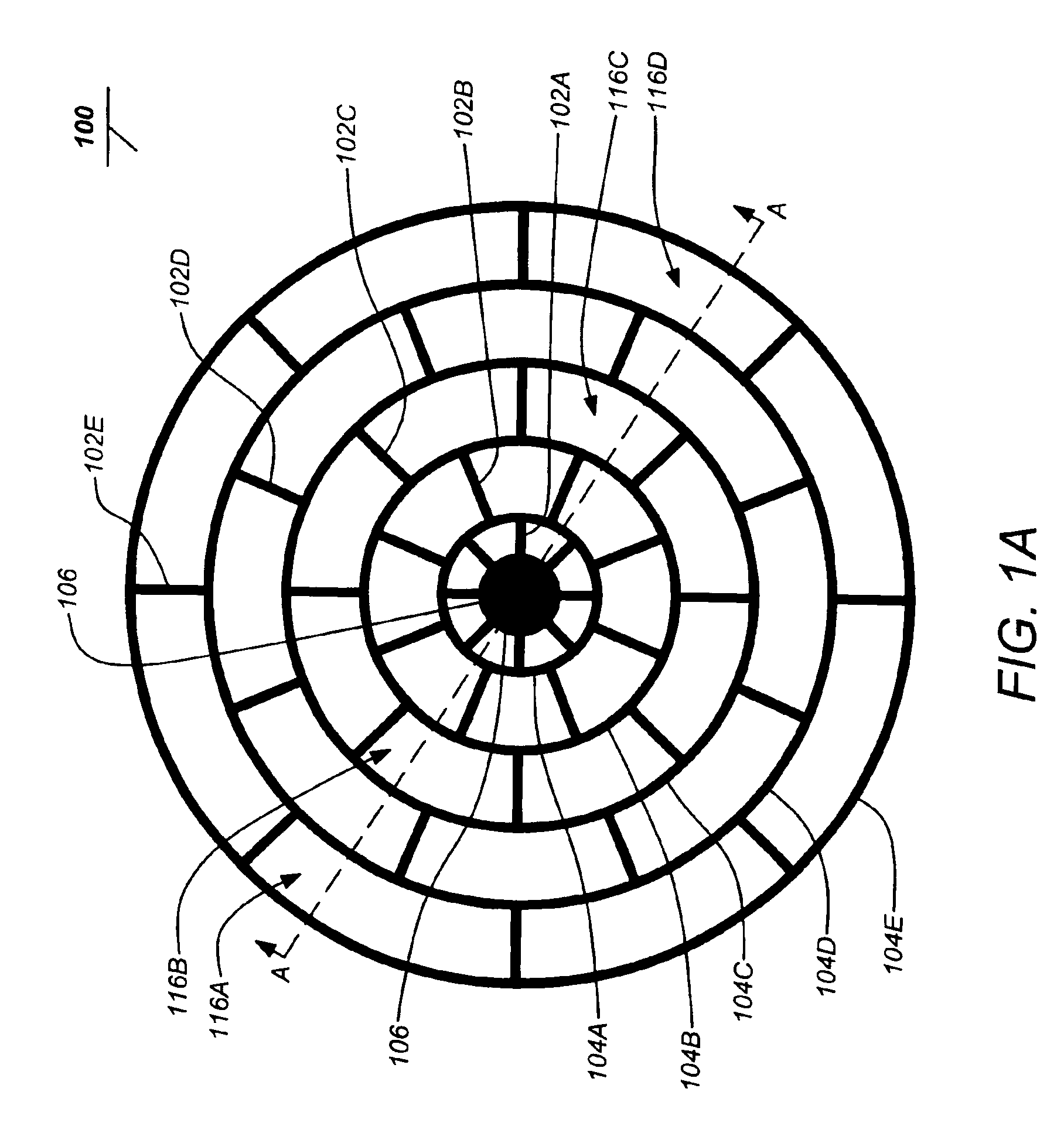
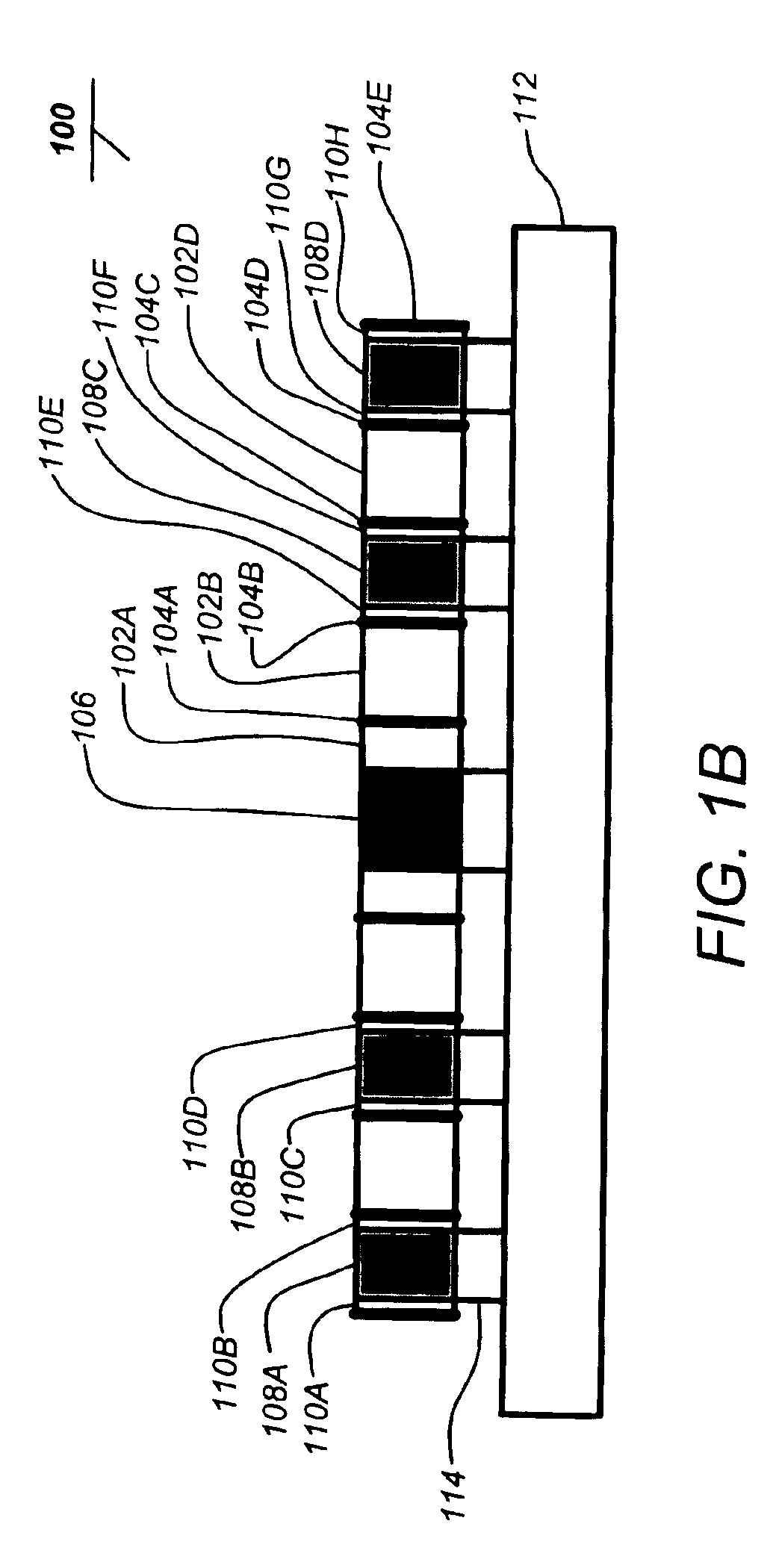
[0055]Embodiments of the present invention generally describe an isolated planar vibratory gyroscope. Generally, embodiments of the invention employ embedded sensing and actuation providing a planar micromachined silicon gyroscope having desirable axisymmetric resonator with single central nodal support, integral (and distributed) proof mass and flexural suspension and extensive capacitive electrodes with large total area. Advantageously, the entire resonator, embedded electrodes and integral case wall of the present invention can be fabricated from a single wafer of silicon.

[00...


PUM

PropertyMeasurementUnit
diameteraaaaaaaaaa
diameteraaaaaaaaaa
strain energyaaaaaaaaaa

Abstract

The present invention discloses an inertial sensor having an integral resonator. A typical sensor comprises a planar mechanical resonator for sensing motion of the inertial sensor and a case for housing the resonator. The resonator and a wall of the case are defined through an etching process. A typical method of producing the resonator includes etching a baseplate, bonding a wafer to the etched baseplate, through etching the wafer to form a planar mechanical resonator and the wall of the case and bonding an end cap wafer to the wall to complete the case.

Description

CROSS-REFERENCE TO RELATED APPLICATIONS[0001]This application claims the benefit under 35 U.S.C. §119(e) of the following U.S. provisional patent applications, which are all incorporated by reference herein:[0002]U.S. Provisional Patent Application No. 60 / 402,681, filed Aug. 12, 2002, and entitled “CYLINDER GYROSCOPE WITH INTEGRAL SENSING AND ACTUATION”, by Kirill V. Shcheglov and A. Dorian Challoner; and[0003]U.S. Provisional Patent Application No. 60 / 428,451, filed Nov. 22, 2002, and entitled “DESIGN AND FABRICATION PROCESS FOR A NOVEL HIGH PERFORMANCE MESOGYRO”, by Kirill V. Shcheglov and A. Dorian Challoner.[0004]This application is related to the following co-pending applications, which are all incorporated by reference herein:[0005]U.S. patent application Ser. No. 09 / 928,279, filed Aug. 10, 2001, and entitled “ISOLATED RESONATOR GYROSCOPE”, by A. Dorian Challoner which issued Oct. 7, 2003 as U.S. Pat. No. 6,629,460;[0006]U.S. patent application No. 10 / 370,953, filed Feb. 20, 2...

Claims


Application Information

Patent Timeline
Patent Type & Authority Patents(United States)
IPC IPC(8): B81C3/00G01C19/56G01C19/5684
CPCB81C3/001G01C19/5684Y10T29/4902Y10T29/49002Y10T29/49007
Inventor SHCHEGLOV, KIRILL V.CHALLONER, A. DORIANHAYWORTH, KEN J.WIBERG, DEAN V.YEE, KARL Y.
Owner CALIFORNIA INST OF TECH
Why Eureka
Try Eureka