Regasification system and method

a liquid natural gas and gasification system technology, applied in the direction of gas/liquid distribution and storage, ventilation/heating/cooling of vessels, auxiliaries, etc., can solve the problems of either unprofitable economic or technical difficulties in laying pipelines

Inactive Publication Date: 2005-09-20
WARTSILA OIL & GAS SYST
View PDF5 Cites 58 Cited by
  • Summary
  • Abstract
  • Description
  • Claims
  • Application Information

AI Technical Summary

Problems solved by technology

In many instances, however, the reservoirs are located in remote areas and / or areas with restricted accessibility, such that laying a pipeline is either technically very complicated and / or economically unprofitable.

Method used


Image

  • Regasification system and method
  • Regasification system and method
  • Regasification system and method

Examples


Embodiment Construction

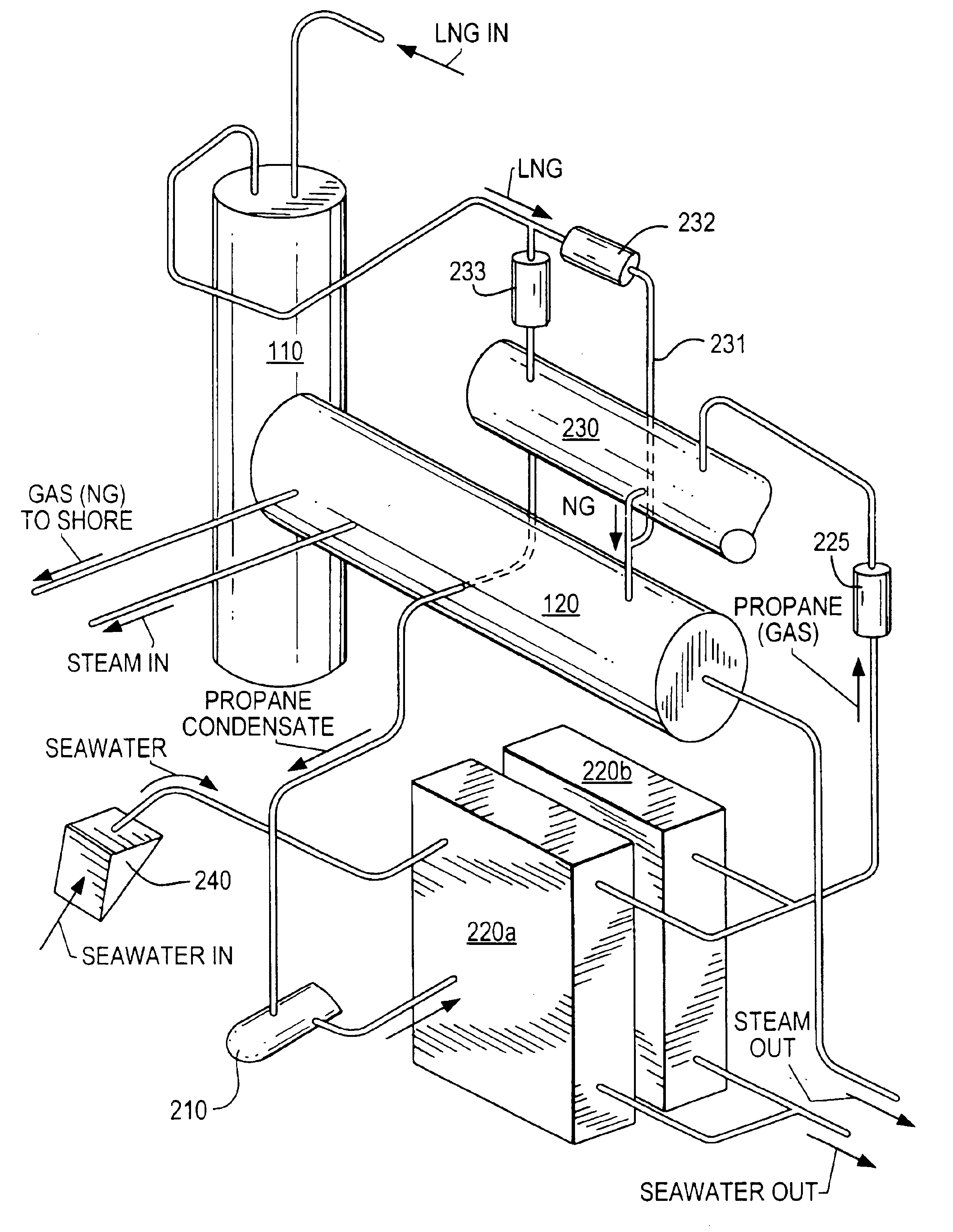
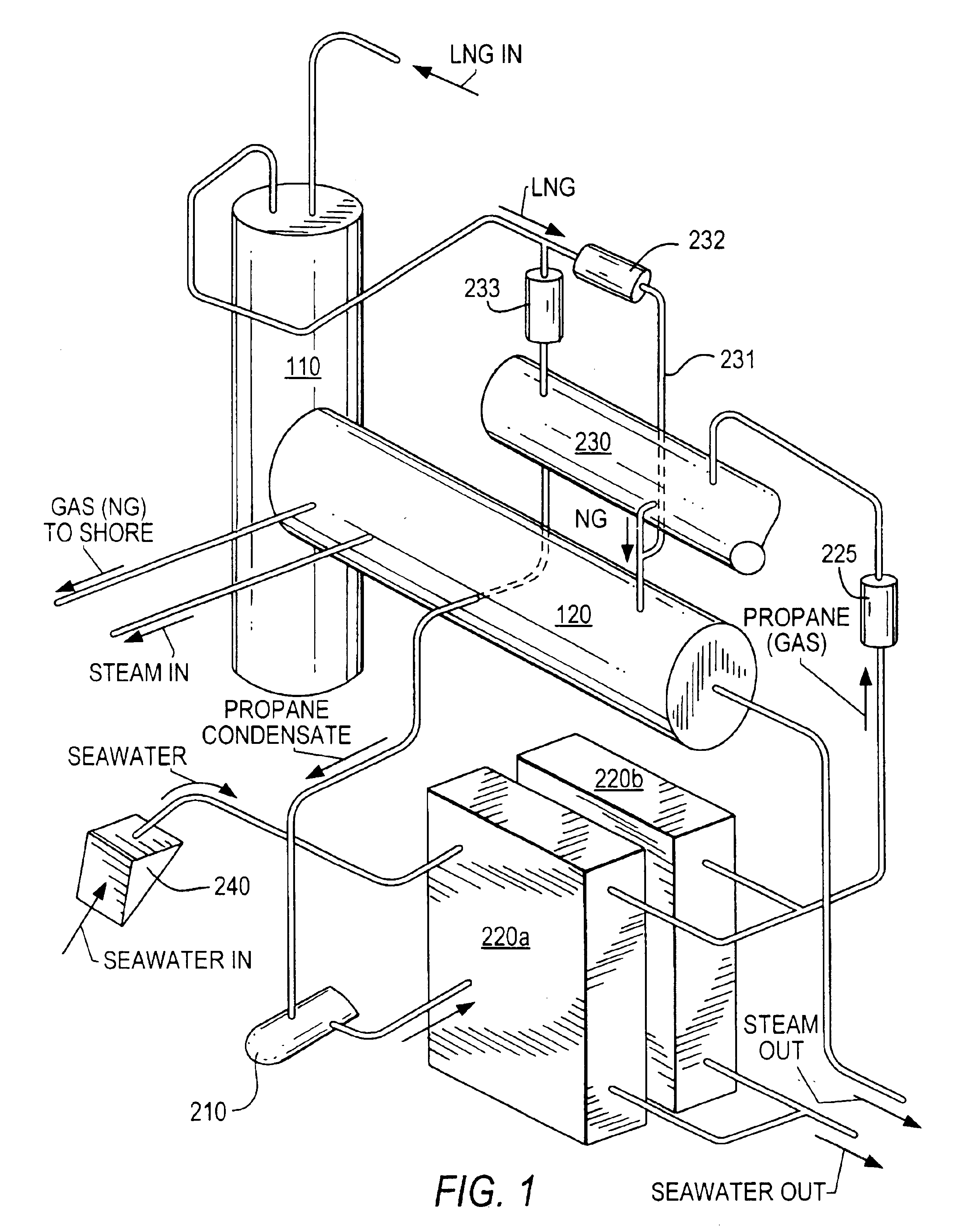
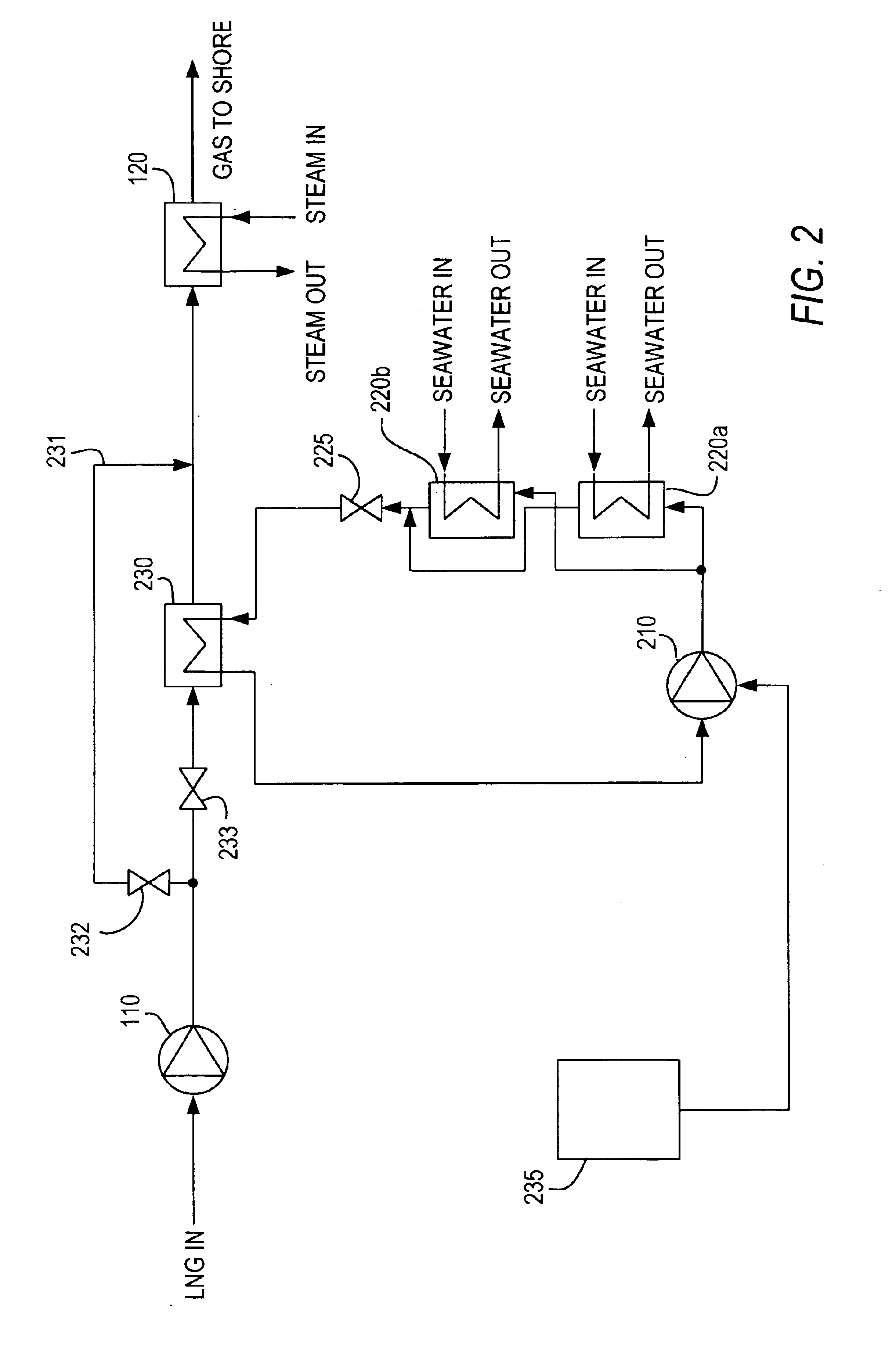
[0036]An embodiment of the regasification system according to the present invention will now be described in detail. The regasification system comprises basically two circuits: a coolant circuit and a natural gas circuit. Propane is often preferred as a coolant, but any fluid having an evaporation temperature of about 0° C. in the pressure ranges 2 to 25 bar may be suitable.

[0037]As shown in the figures, the LNG (e.g. methane) is fed from the onboard tanks (not shown) and into a cryogenic booster pump 110 which boosts the LNG pressure, and from which it is flowed into an LNG / coolant heat exchanger 230. Typically—for liquefied methane—the temperature upon entering the LNG / coolant heat exchanger is in the order of −160° C. at a pressure of about 50 to 130 bar. The LNG / coolant heat exchanger 230 may be a stainless steel type compact printed circuit heat exchanger (PCHE).

[0038]The natural gas (NG) leaves the LNG / coolant heat exchanger 230 in an evaporated state (for methane, at a temper...


PUM


Abstract

The present invention provides a novel regasification method and system in which the evaporative coolant is forced through an evaporation and condensation cycle, allowing control of the evaporative coolant condensation pressure; thus yielding a more flexible and more compact regasification system than those of the prior art.

Description

BACKGROUND OF THE INVENTION[0001]1. Field of the Invention[0002]This invention relates to the field of regasification systems, and more specifically to a method and system for regasification of liquid natural gas (LNG), intended for installation on a seagoing vessels.[0003]2. Description of the Related Art[0004]Natural gas exists in subterranean reservoirs throughout the world. This gas (i.e. methane) is a valuable commodity, and various methods and equipment exist for the extraction, treatment and transportation of this natural gas from its reservoir to the consumer. The simplest transportation means is a pipeline for conveying the gas in its gaseous state from the reservoir to the consumer. In many instances, however, the reservoirs are located in remote areas and / or areas with restricted accessibility, such that laying a pipeline is either technically very complicated and / or economically unprofitable. One very common technique for transporting natural gas from such areas, is to l...

Claims


Application Information

Patent Timeline
Patent Type & Authority Patents(United States)
IPC IPC(8): B63J2/00B63J2/14B63J5/00F17C7/04F17C7/00B63J99/00
CPCB63J2/14B63J99/00F17C7/04F17C2265/05F17C2227/0309F17C2221/033F17C2223/0161F17C2223/033F17C2225/0123F17C2225/036F17C2227/0318F17C2227/0323F17C2250/0626F17C2270/0105F17C2270/0113
Inventor MADSEN, PER HELGE
Owner WARTSILA OIL & GAS SYST
Why Eureka
Try Eureka