
Low NOx emission diffusion flame combustor for gas turbines

a technology of diffusion flame and gas turbine, which is applied in the direction of burners, combustion chambers, combustion processes, etc., can solve the problems of limited production of unburned matter, naturally increasing in the diffusion flame, etc., and achieve the effect of reducing the nox emission by a substantial amoun

Inactive Publication Date: 2005-09-20
ENEL PRODUZIONE
View PDF12 Cites 14 Cited by
  • Summary
  • Abstract
  • Description
  • Claims
  • Application Information

AI Technical Summary

Benefits of technology

[0014]It is, therefore, an object of the present invention to provide a combustor for diffusion flame gas turbines that utilizes an optimal distribution of air and fuel in the primary combustion zone so as to lower substantially the NOx emissions relative to conventional combustors.
[0015]Another object of the present invention is to provide a combustor that is suitable for retrofitting to a diffusion flame gas turbine for operation within the power range 15 and 24 Mwe, that has a modest to low impact on the machine, and upon being applied to it, that maintains its original encumbrance, without the necessity of modifying the control system or the fuel supply of the machine.
[0017]In this manner, the present invention increases the presence of air in the primary combustion zone and realizes a partially premixed air-fuel stream to be exposed on the flame front in such a way as to limit temperature peaks, which are among the principal factors promoting the formation of thermal NOx. Moreover, the production of unburned matter-that would naturally increase in the diffusion flame due to attenuation of the primary flame temperature-is limited by the effects of the premixing.

Problems solved by technology

Moreover, the production of unburned matter-that would naturally increase in the diffusion flame due to attenuation of the primary flame temperature-is limited by the effects of the premixing.

Method used


Image

  • Low NOx emission diffusion flame combustor for gas turbines
  • Low NOx emission diffusion flame combustor for gas turbines
  • Low NOx emission diffusion flame combustor for gas turbines

Examples


Embodiment Construction

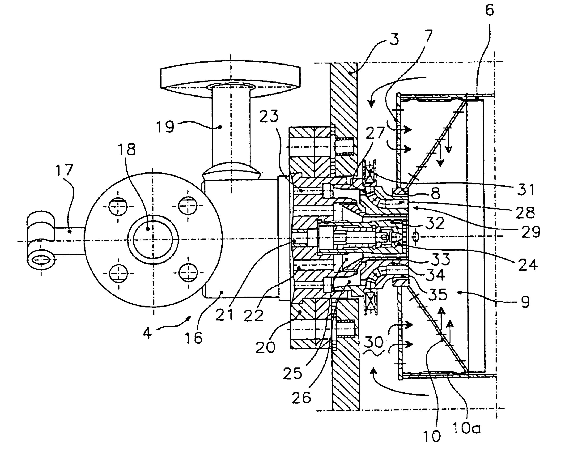
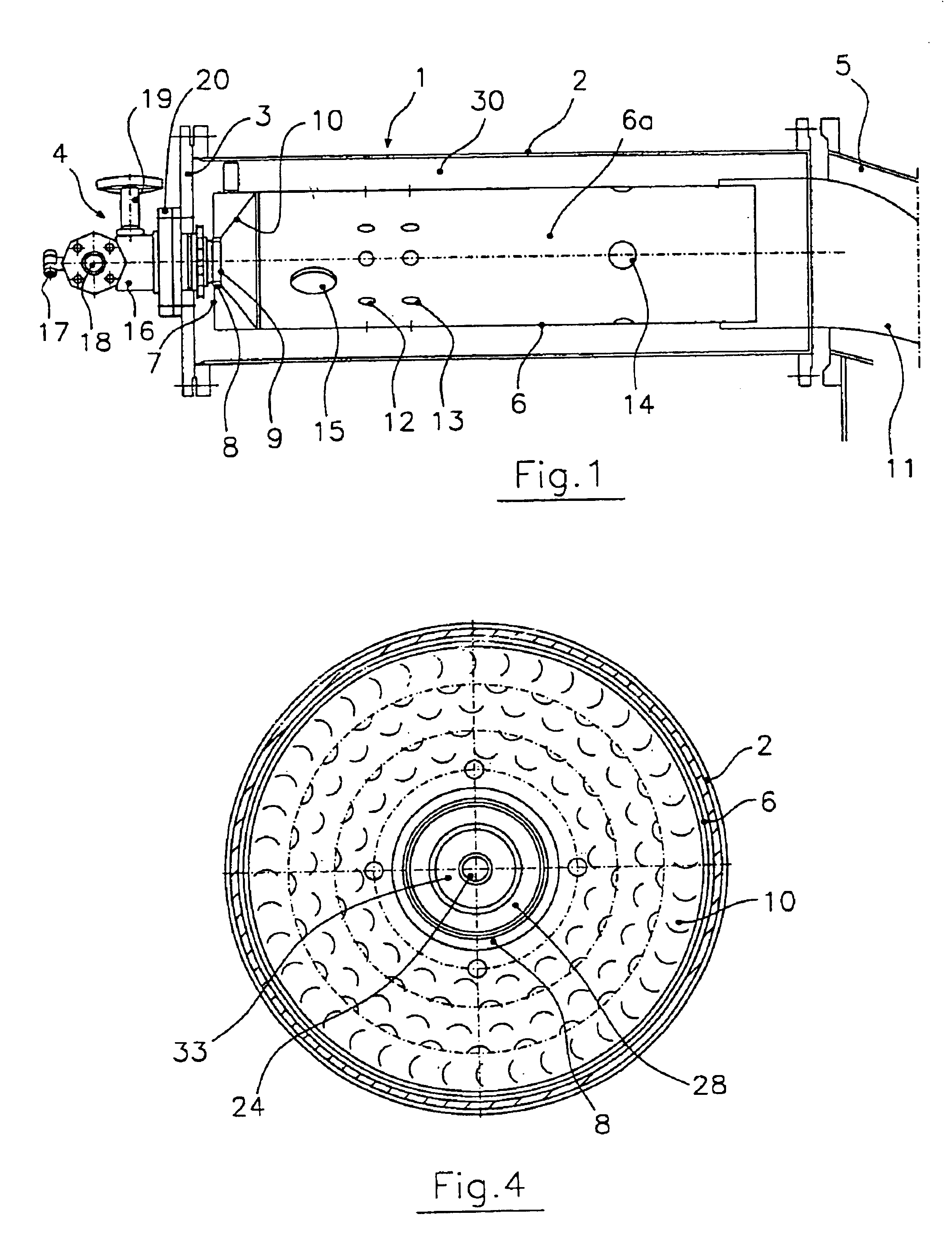
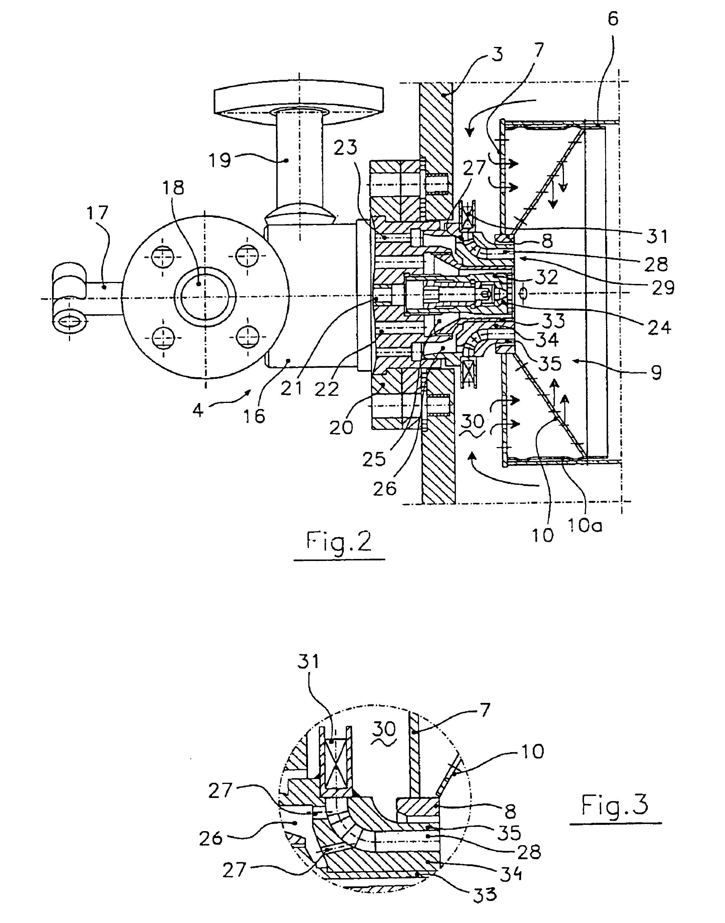
[0025]Referring now to the drawings and, more particularly, to FIGS. 1-6, there is shown generally a low NOx emission diffusion flame combustor for gas turbines or the like, according to various aspects of the present invention. According to one embodiment, illustrated generally in FIG. 1, a generic combustor unit 1 of a gas turbine is shown, which comprises an outer tubular container 2 closed at one end by a cover 3, at the center of which an injector unit 4 is affixed or mounted. The other end of tubular container 2 communicates with a discharge box 5 of a combustion air compressor (not shown). A flame tube 6 arranged coaxially with tubular container 2 delimits a combustion chamber 6a closed at one end by a calibrated plate 7. The plate is uniformly perforated and has, at its center, a ferrule 8 for engaging head 9 of the injector unit. Notably, the combustor, in accordance with the present invention, is particularly suitable for retrofitting to industrial-type gas turbines with c...


PUM


Abstract

A diffusion flame combustor for a gas turbine comprising a flame tube that delimits a combustion chamber, the flame tube having a fuel injector unit mounted at one end, the other end of the tube being connected to a duct that conveys combustion gases to the turbine. The flame tube is mounted coaxially inside a generally tubular container that communicates with the discharge casing of an air compressor and, together with the tube, defines a space for combustion air. The injector unit comprises an injector head facing generally into the combustion chamber and provided with at least one fuel gas injection nozzle. The nozzle includes an air-gas premixing duct into which fuel gas is introduced. The premixing duct has an inlet section that communicates with the air space and is provided with a radial-fin air swirler generally upstream of a point at which the fuel gas enters the premixing duct. This partial premixing of combustion gas with combustion air reduces NOx emissions and production of un-combusted material.

Description

FIELD OF THE INVENTION[0001]The present invention relates generally to pollution control and, more particularly, to an arrangement for reducing emissions from a diffusion flame combustor for a gas turbine or the like.BACKGROUND OF THE INVENTION[0002]Conventional diffusion flame combustors for gas turbines typically comprise a fuel injector unit mounted at one end of a flame tube that delimits a combustion chamber. The other end of the tube is connected to a duct for conveying combustion gas to the turbine blades. The flame tube is mounted coaxially within a tubular container that is in communication with a combustion air compressor discharge casing and, together with the flame tube, defines a space for combustion air, or air space. The injector unit is mounted so as to have its head inside the combustion chamber and is provided, in a two-fuel version, for example, with an axial atomizer nozzle for the liquid fuel and, around it, an annular injector nozzle or a crown of nozzles for i...

Claims


Application Information

Patent Timeline
IPC IPC(8): F23R3/14F23R3/28F23R3/04
CPCF23R3/14F23R3/286F23D2900/00008
Inventor BENELLI, GIANCARLOCARRAI, LUCIANOCECCHINI, DAVIDETANZINI, GIORDANO
Owner ENEL PRODUZIONE
Learn More