Scanning probe microscope with improved probe tip mount

Inactive Publication Date: 2005-09-20
PARK SYST CORP
View PDF25 Cites 20 Cited by
  • Summary
  • Abstract
  • Description
  • Claims
  • Application Information

AI Technical Summary

Benefits of technology

[0012]A scanning probe microscope in accordance with the invention uses two different scanners that are completely detached each from the other, and are physically mounted at separate locations on a stationary frame. One scanner (called “x-y scanner”) scans a sample in a plane (also called “x-y plane”), while the other scanner (called “z scanner”) scans a probe tip (which is supported at a free end of a cantilever) in a direction (also called “z direction”) perpendicular to the plane. Detachment of the two scanners from one another ensures that each scanner can be moved (relative to the frame) without affecting the other scanner.

Problems solved by technology

A probing unit, including such an aligning mechanism plus the laser, PSPD, and cantilever, has considerable mass and it is difficult for the AFM to scan the probing unit at sufficiently high speed while maintaining accuracy.
Such scan speed is acceptable but not satisfactory for the reasons discussed below.
However, large samples, such as large silicon wafers, cannot be scanned fast enough e.g. 1 KHz in z direction for sufficient vertical servo frequency response.
However, such a miniaturized probing unit still has a considerable mass and it degrades the z servo response.
It is also inconvenient to align the laser beam with tiny screws and a special tool had to be used.
However in this method, the laser beam does not perfectly follow the cantilever and the reflected beam does not remain on the exact same point on the PSPD, causing measurement errors and tracking force variations during x-y scan.
In addition, most AFMs have the common problems of scanning errors and slow scanning speed.
However, z cross talk from flexing the tube cannot be eliminated and it causes background curvature effect and measurement errors.
Using a tripod scanner does not improve the non-linearity and cross talk problem much.
However, since the z scanner described by Braunstein et al. is attached to the x-y scanner, the z scanner cannot move faster than the resonance frequency of the x-y scanner, which is about 100 Hz.
However, the vertical servo frequency response cannot be higher than the resonance frequency of the z scanning system. z-scanning system means the z scanner and the supporting structure for the z scanner plus whatever the z scanner has to move in z direction.
The micro-machined cantilever is attached on a small chip (2×4 mm), and it is difficult to handle even with a tweezers.
), a magnet was used to hold the chip mount but the chip mount sit directly on the magnet, which does not ensure the same cantilever position after replacement.

Method used


Image

  • Scanning probe microscope with improved probe tip mount
  • Scanning probe microscope with improved probe tip mount
  • Scanning probe microscope with improved probe tip mount

Examples


Embodiment Construction

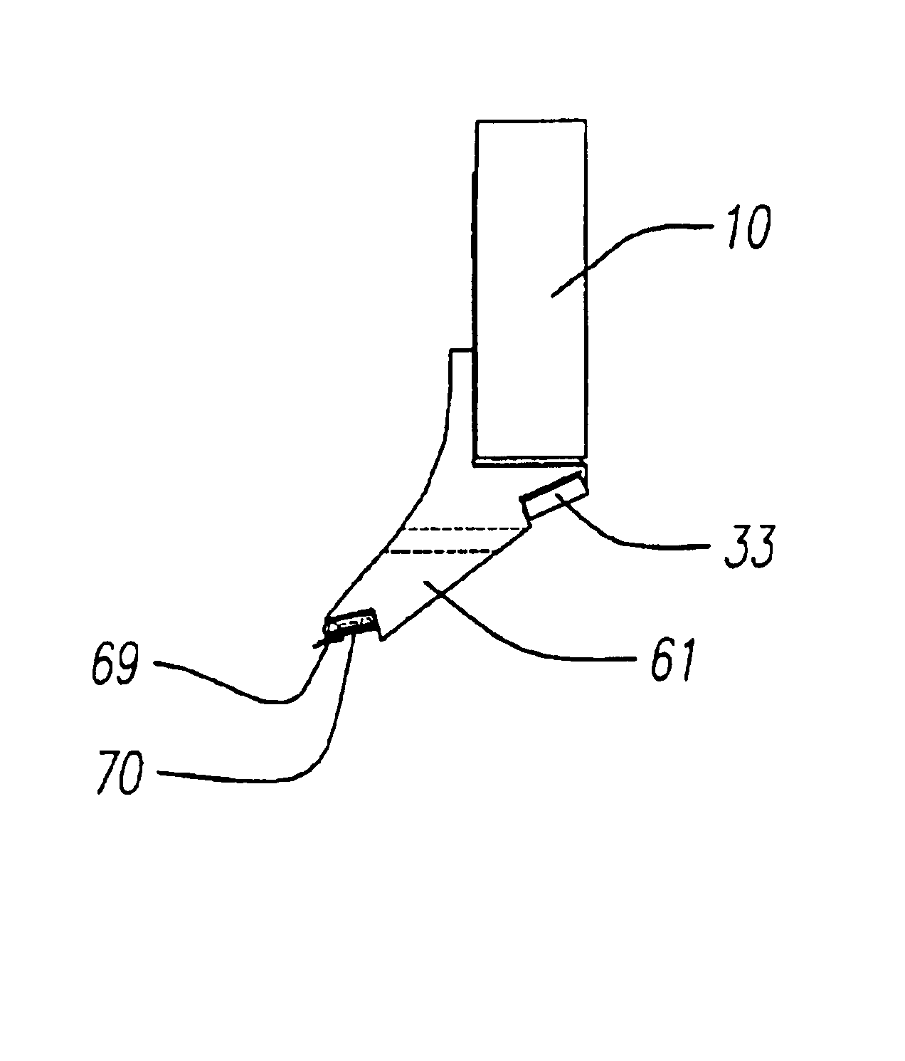
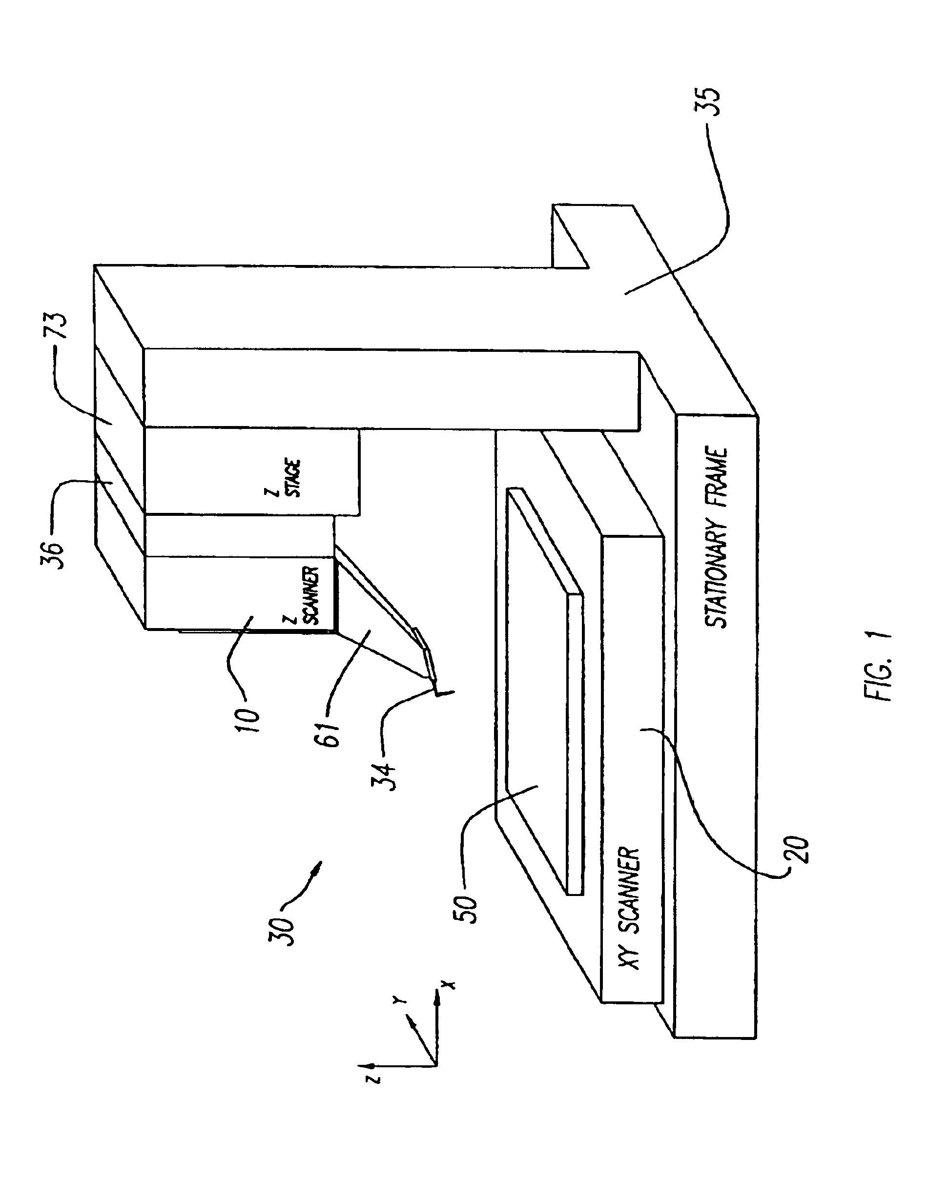
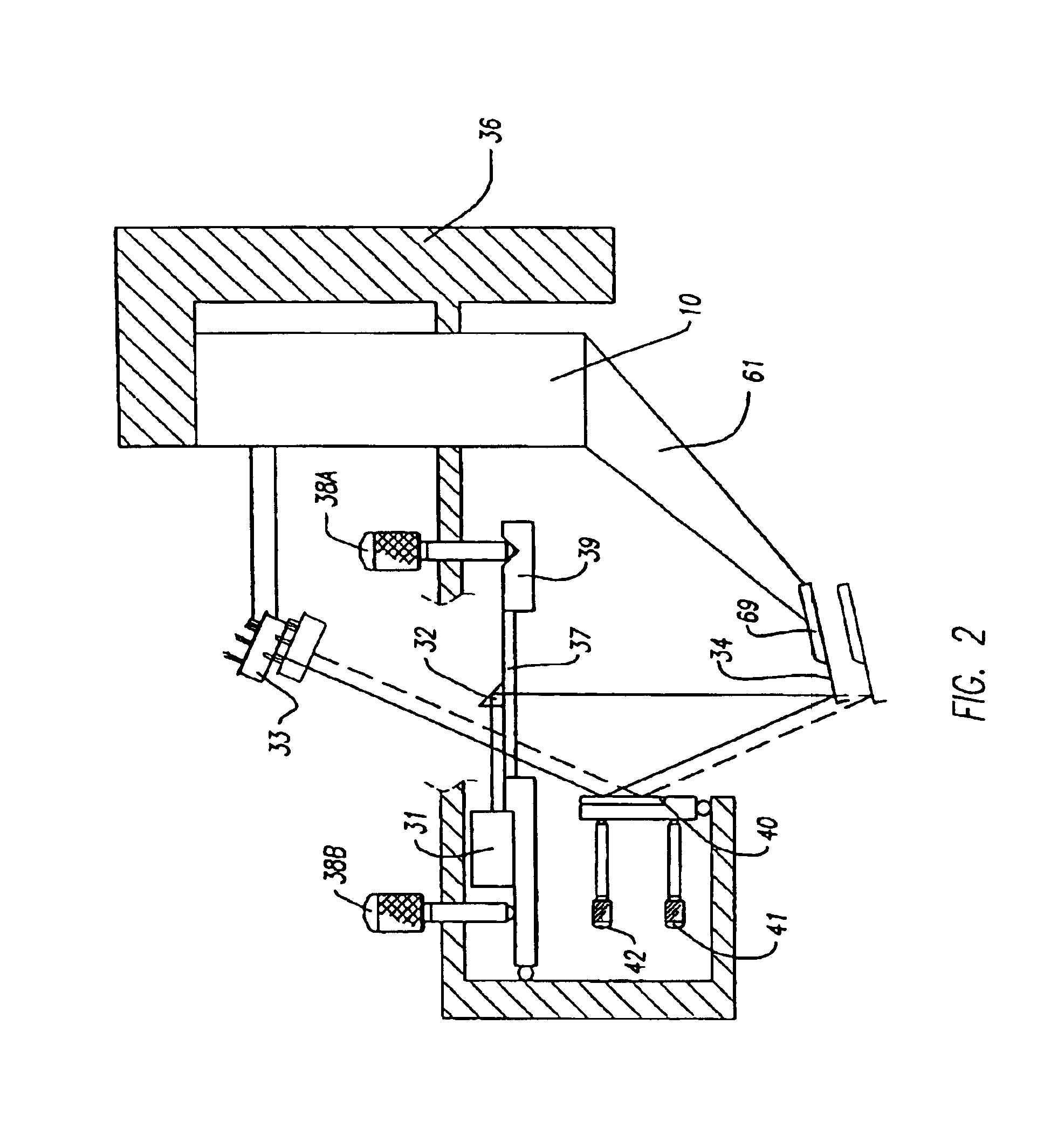
[0026]A scanning probe microscope 30 in accordance with the invention physically separates a z scanner 10 from an x-y scanner 20, as shown in FIG. 1. Scanners 10 and 20 are mounted on a common frame 35 that is stationary, although in an alternative embodiment, they may be mounted on different frames. There is also a z-stage 73 between scanner 10 and scanner 20. The z-stage 73 is a one dimensional translation stage with a stepper motor and is used to bring a probe tip (mounted on a cantilever that in turn is mounted on a z scanner) close enough to a sample on a sample chuck 50 so that the sample surface can be reached within z scanner range. Regardless of how they are mounted, the two scanners 10 and 20 are physically detached from one another (i.e. are not mechanically coupled, except that both are coupled to a stationary frame 35 and each provides motion relative to the frame independent of the other).

[0027]Such physical separation of x-y scanner 20 from z scanner 10, in a scanning...


PUM


Abstract

A mounting mechanism for the probe tip of a Scanning Probe Microscope (SPM) includes a scanner supported by a stationary frame, and a kinematic mechanism supported by the scanner. The kinematic mechanism includes at least three protrusions and at least one magnet. The mounting mechanism for the probe tip also includes a chip mount having a hole, a slot and a flat surface. The chip mount, on being held by the magnet, provides an easy way to mount the probe tip without requiring any tools.

Description

[0001]This application is a continuation of U.S. patent application Ser. No. 10 / 077,835 filed on Feb. 15, 2002, now U.S. Pat. No. 6,677,567 by Jaewan Hong et al, that is incorporated by reference herein In its entirety.BACKGROUND OF THE INVENTION[0002]The Scanning Probe Microscope (SPM) is a powerful instrument in the nanometer scale science and technology. Among the many variations of SPM, the Atomic Force Microscope (AFM) is the most widely used and the most fundamental version. One prior art AFM is described in an article by G. Binnig, C. Quate, and Ch. Gerber in Phys. Rev. Lett. 56, 930 (1986). AFM has evolved since then, refining its capabilities and conveniences. In a commonly used configuration, a prior art AFM has a micro-machined cantilever with a sharp tip on its edge, and the AFM scans the sample or the cantilever with a piezoelectric tube. The deflection of the cantilever is measured by the AFM casting a laser beam on the cantilever and detecting the reflected beam with ...

Claims


Application Information

Patent Timeline
IPC IPC(8): G12B21/22G12B21/00G12B21/08G12B21/02G01Q10/02G01Q10/04G01B21/30G01Q20/02G01Q30/00G01Q60/32G01Q60/38G01Q70/02G01Q70/10H01J37/26
CPCB82Y35/00G01Q10/02G01Q10/04G01Q20/02G01Q70/02Y10S977/869Y10S977/881Y10S977/849Y10S977/732Y10S977/873Y10S977/87H01J37/26
Inventor KWON, JOONHYUNGKIM, YOUNG SEOKPARK, SANG-IL
Owner PARK SYST CORP
Why Eureka
Try Eureka