Eureka AIR delivers breakthrough ideas for toughest innovation challenges, trusted by R&D personnel around the world.

Miniature garbage incinerator and method for incineration

a technology of incinerators and garbage, applied in the direction of capillary burners, combustion types, lighting and heating apparatus, etc., can solve the problems of limited or no value, fire hazards, etc., and achieve the effect of saving energy

Inactive Publication Date: 2005-09-20
KHYMYCH VASYL
View PDF18 Cites 16 Cited by
  • Summary
  • Abstract
  • Description
  • Claims
  • Application Information

AI Technical Summary

Benefits of technology

"The present invention provides an incineration method and a portable incinerator for garbage disposal that can be easily used by a common person without any special training. The device does not require a separate fuel supply and is safe and energy efficient. It is small enough to be used both in a stationary mode as well as a mobile mode and can be located outside the house or in the basement. The device has a furnace chamber equipped with an electric heater that heats up the garbage to the point of spontaneous combustion and a filtration unit with two stages of filtration to remove pollutants and exhaust particles from the exhaust gases. The gases are then re-circulated back into the furnace chamber to save energy and complete the incineration process."

Problems solved by technology

Otherwise, it will be of limited or no value due to the complexity of refueling such a device.
Individual homeowners frequently resort to open burning either on the ground or in a barrel-like container which creates a fire hazard due to flying sparks, hot ashes and the like.
The above mentioned and other patents of the prior art do not address the need to provide a safe, small, portable and clean burning incinerator, which is easy to use by a non-trained person and can be used in every day life with high reliability and without a need for separate fuel supply.

Method used


Image

  • Miniature garbage incinerator and method for incineration
  • Miniature garbage incinerator and method for incineration
  • Miniature garbage incinerator and method for incineration

Examples


Embodiment Construction

[0036]A detailed description of the present invention follows with reference to accompanying drawings in which like elements are indicated by like reference letters and numerals.

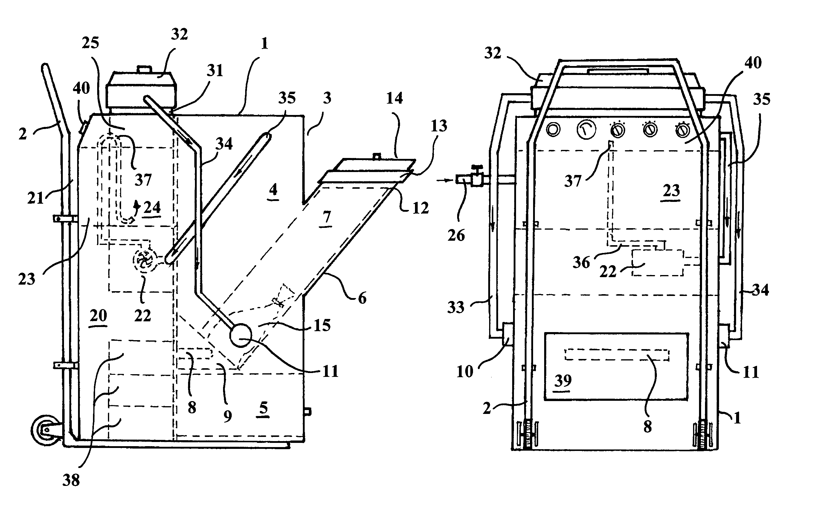
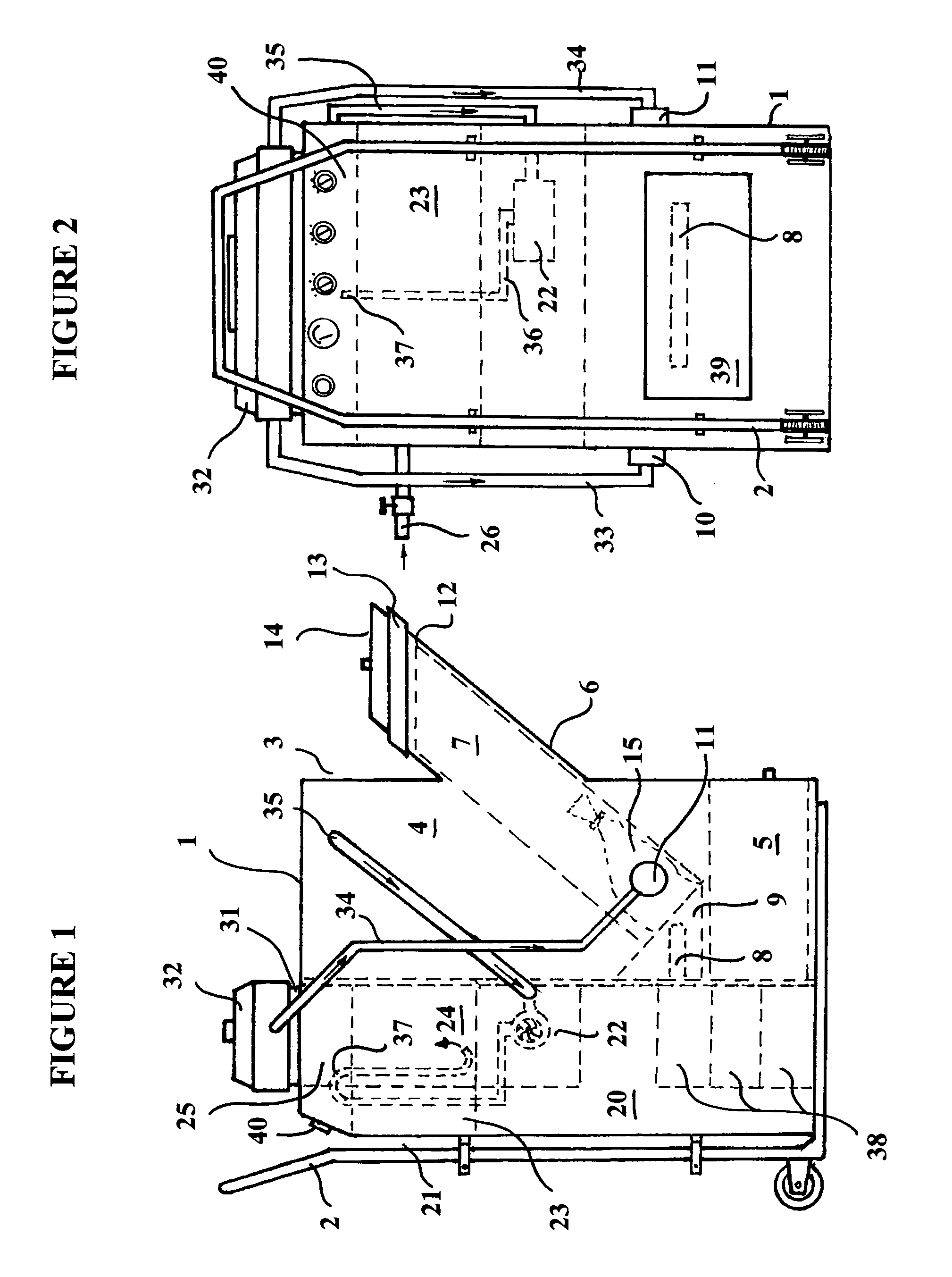
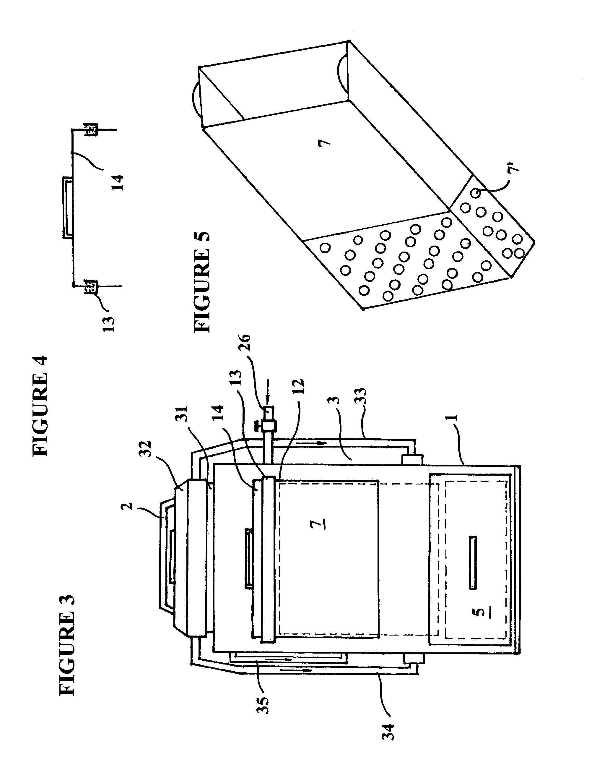
[0037]The miniature garbage incinerator of the present invention is shown in general on FIGS. 1, 2, and 3. It consists of a housing 1 mounted on a wheeled hand-truck assembly 2 so that it can be easily transported from place to place. The housing 1 contains both main components of the device: incineration block 3 and filtration block 20.

[0038]Incineration block 3 in turn is located in the back portion of the incinerator. It consists of a furnace chamber 4 and a retractable drawer 5 located underneath thereof for removal of the portion of the waste that could not be burned. The details of these elements can be best seen on FIGS. 1 and 2.

[0039]The furnace chamber 4 contains an inclined hopper 6 including a retractable extender 7, as well as a heating element 8 located inside its own enclosure 9 along with two ...


PUM


Abstract

A portable miniature incinerator is described allowing easy disposal of household garbage for a single-family house or a small apartment building. The housing of the incinerator is mounted on a wheeled hand-truck assembly and contains an incineration block and a filtration block. The incineration block in turn comprises a furnace chamber equipped with an electric heater. The heater is adapted to bring the temperature of the air and therefore the temperature of the garbage up to the point of spontaneous combustion. During the process of heating up the garbage, it becomes dry as the fans of the device remove all water evaporation. Once ignited, the garbage is incinerated in the furnace chamber while all exhaust gases are directed to the filtration unit. The filtration unit has a first stage of filtration comprising a wire mesh separator submerged in water. Exhaust gases pass through the mesh separator and through the water so that the pollutants and exhaust particles are separated from the exhaust gases. Following that first filtration stage, the exhaust gases are sent toward the second cleaning stage, this stage being a fabric-filled gas filter, for complete separation of all impurities. The gases are then directed back towards the furnace chamber to re-circulate the flow of hot gases and save energy. That process continues until the incineration is complete.

Description

BACKGROUND OF THE INVENTION[0001]The present invention relates generally to an incineration method and a miniature garbage incinerator. The device of the invention contains provisions for electrical igniting of the garbage, its complete burning in the enclosed chamber and removal of harmful particulate from the exhaust gases before releasing them into atmosphere. The incinerator of the invention may be advantageously used for small waste incineration needs such as with single-family houses and small buildings. It can be easily transported from one site to the next.[0002]Incineration has been determined to be the best way to deal with garbage. Many different types of waste incinerators and furnaces have been proposed in the past. For the most part, these are the large-scale industrial waste treating plants. Garbage is delivered to these sites for burning and further disposal. These devices require supply of fuel and exhaust treatment facilities to prevent polluting the atmosphere wit...

Claims


Application Information

Patent Timeline
Patent Type & Authority Patents(United States)
IPC IPC(8): F23J15/00F23G5/08F23G5/10F23C9/00F23G5/40F23J1/00F23J15/02
CPCF23G5/10F23G5/40F23J1/00F23J15/022F23G2205/14F23G2900/00001F23J2217/30
Inventor KHYMYCH, VASYL
Owner KHYMYCH VASYL
Why Eureka
Eureka Blog
Learn More