Method of contactlessly monitoring elevator shaft doors

a technology of elevator shaft and door, which is applied in the direction of elevators, transportation and packaging, building lifts, etc., can solve the problems of high voltage decay, inability to detect defective safety contact of individuals, and inability to find incorrectly closed shaft doors in buildings with many floors, so as to reduce production costs, reduce sensitivity, and simplify the effect of beam system

Active Publication Date: 2005-09-20
INVENTIO AG
View PDF14 Cites 24 Cited by
  • Summary
  • Abstract
  • Description
  • Claims
  • Application Information

AI Technical Summary

Benefits of technology

[0019]Advantageously, shaft door monitoring sensors are used which emit light beams in the wavelength ranges of ultraviolet light, visible light or infrared light. Such sensors are available commercially and have the advantage that the beam path is visible by eye or is able to be checked by simple sensors.
[0020]According to a particularly simple embodiment of the method according to the present invention the beam is emitted by an emitter which is preferably arranged in the region of a shaft end (for example, in the shaft head) and received and evaluated by a receiver which is preferably arranged in the region of the other shaft end (for example, in the shaft pit). Such an arrangement, which is designated emitter / receiver principle in the following, has the shortest possible length of the beam path, which allows use of simpler and more economic beam systems, does not require complicated alignment of a reflection surface and minimizes sensitivity with respect to contamination. As already mentioned, the requisite monitoring length can also be achieved by arrangement of several segments in succession each with a respective emitter / receiver system.
[0021]According to a further embodiment of the present invention, the beam is emitted by an emitter, which is preferably mounted in the region of one shaft end, in the direction of a reflection surface, which is preferably mounted in the region of the opposite shaft end and from where the beam is reflected to a receiver present in the region of the emitter, wherein the receiver detects whether the beam reaches the receiver or is interrupted as a consequence of a shaft door panel which is not completely closed or a shaft door lock which is not disposed in locking setting. Advantageously, in the case of this method, which is termed reflection principle in the following, emitter and receiver are integrated in a single apparatus, which reduces production costs for the shaft door monitoring sensor and substantially simplifies installation in the shaft. In addition, in the case of this method variant the necessary monitoring lengths can be achieved by arrangement of several monitoring segments in succession each with a respective shaft door monitoring sensor according to the reflection principle.
[0022]A particularly advantageous development of the method according to the present invention consists in constructing the shaft door monitoring sensor as a distance measuring instrument, for example in the form of a laser distance measuring instrument. In that case the beam is emitted at least during the detection phases by an emitter, which is preferably mounted in the region of one shaft end, in the direction of a main reflection surface, which is preferably mounted in the region of the opposite shaft end, so that the beam is reflected by this main reflection surface or by a reflection surface, which is formed by a mechanical component connected with the associated shaft door panel or the shaft door lock and which protrudes into the beam when a shaft door panel is not completely closed and / or a shaft door lock is not disposed in locking setting, to a receiver present in the region of the emitter. Emitter and the receiver of the beam are constructed so that the distance covered by the beam on its path from the emitter back to the receiver by way of one of the reflection surfaces can be ascertained. This embodiment of the method has the advantage that it can not only be established whether one of the shaft door panels is not completely closed and / or one of the shaft door locks is not disposed in locking setting, but that it can also be ascertained on the basis of the measured distance where, i.e. at which floor, the source of disturbance is disposed. The division of the necessary monitoring length into several segments is also possible in the case of this method variant.

Problems solved by technology

Such safety circuits, which in the case of high buildings can comprise a serial connection of more than twenty safety contacts, are known as one of the principal causes of disturbances in elevator operation.
Due to corrosion and contamination the contact resistance of the individual safety contacts increases in a relatively short time, which in the case of serial connection of several contacts causes such a high voltage decay that the safety circuit system switches off the elevator even when the doors are correctly closed.
Moreover, the investigation to find an individual defective safety contact or to find an incorrectly closed shaft door in a building with many floors is extremely time-consuming.
Additional problems with the monitoring of shaft doors have resulted in recent years from persons who enter the elevator shaft in unauthorized manner, whether it be to undertake highly risky “elevator surfing” or to block the elevator car between two floors and threaten or rob elevator passengers.
If the elevator car is disposed at the floor with the unclosed shaft door, then the light beam of the sensor is reflected by the rear car wall so that the sensor correctly does not detect an impermissible state.
Such a shaft door monitoring system does indeed solve some of the afore-described problems, but has certain deficiencies.
Moreover, reliable functioning of the photoelectric detectors could be prejudiced by the fact that a person or an object disposed in front of the door gap of an incompletely closed shaft door reflects the light beam issuing into the elevator lobby and thus renders the monitoring system ineffective.
In addition, a strong light source in the elevator lobby could impair reliable functioning of the sensor in the case of an incompletely closed shaft door.
Further disadvantages result from the fact that a contact-free sensor has to be present at each floor.
In the case of buildings with a large number of floors, an increased susceptibility to disturbance is inevitably caused by the correspondingly large number of sensors and the cost of periodic checking of the sensors is considerable.
In addition, high costs arise for acquisition and installation of this multiplicity of sensors.

Method used


Image

  • Method of contactlessly monitoring elevator shaft doors
  • Method of contactlessly monitoring elevator shaft doors
  • Method of contactlessly monitoring elevator shaft doors

Examples


Embodiment Construction

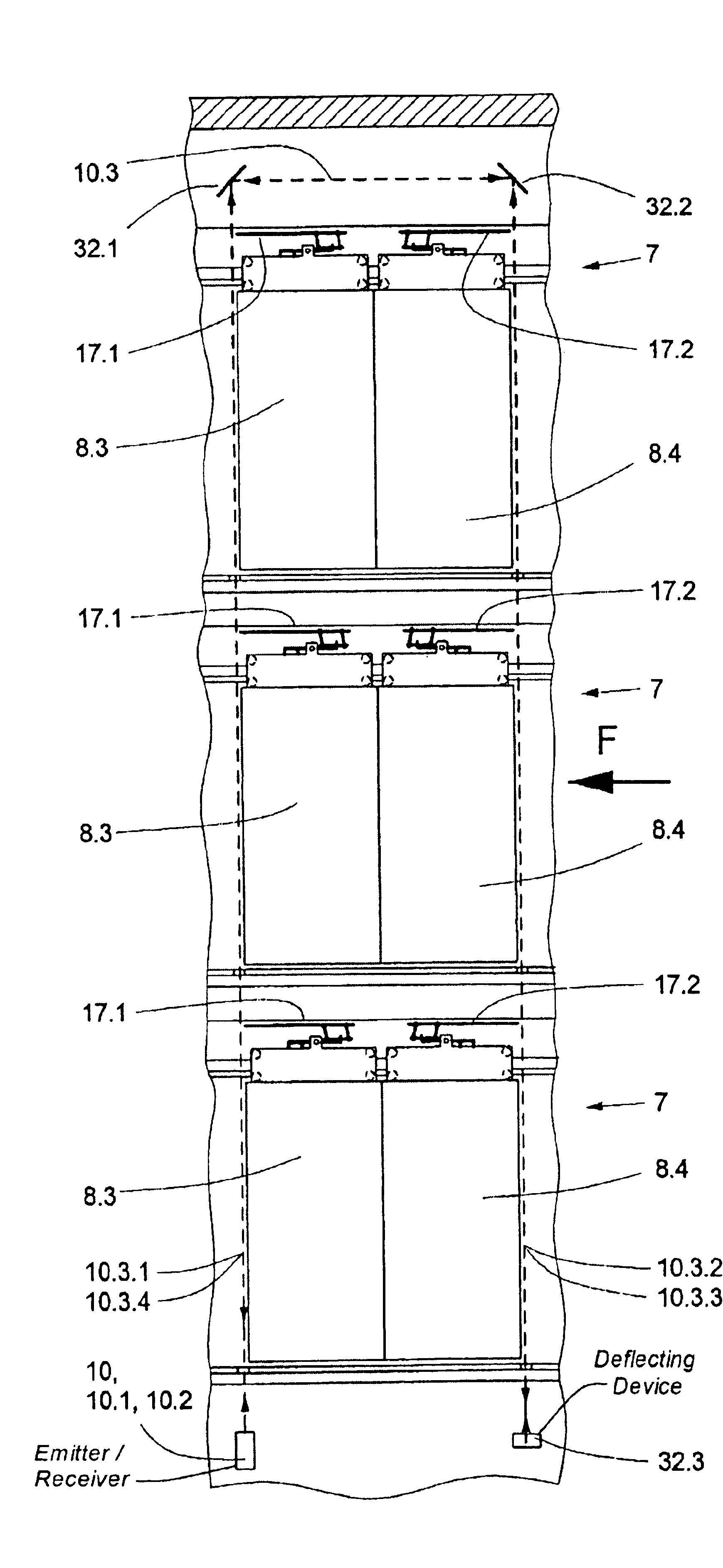
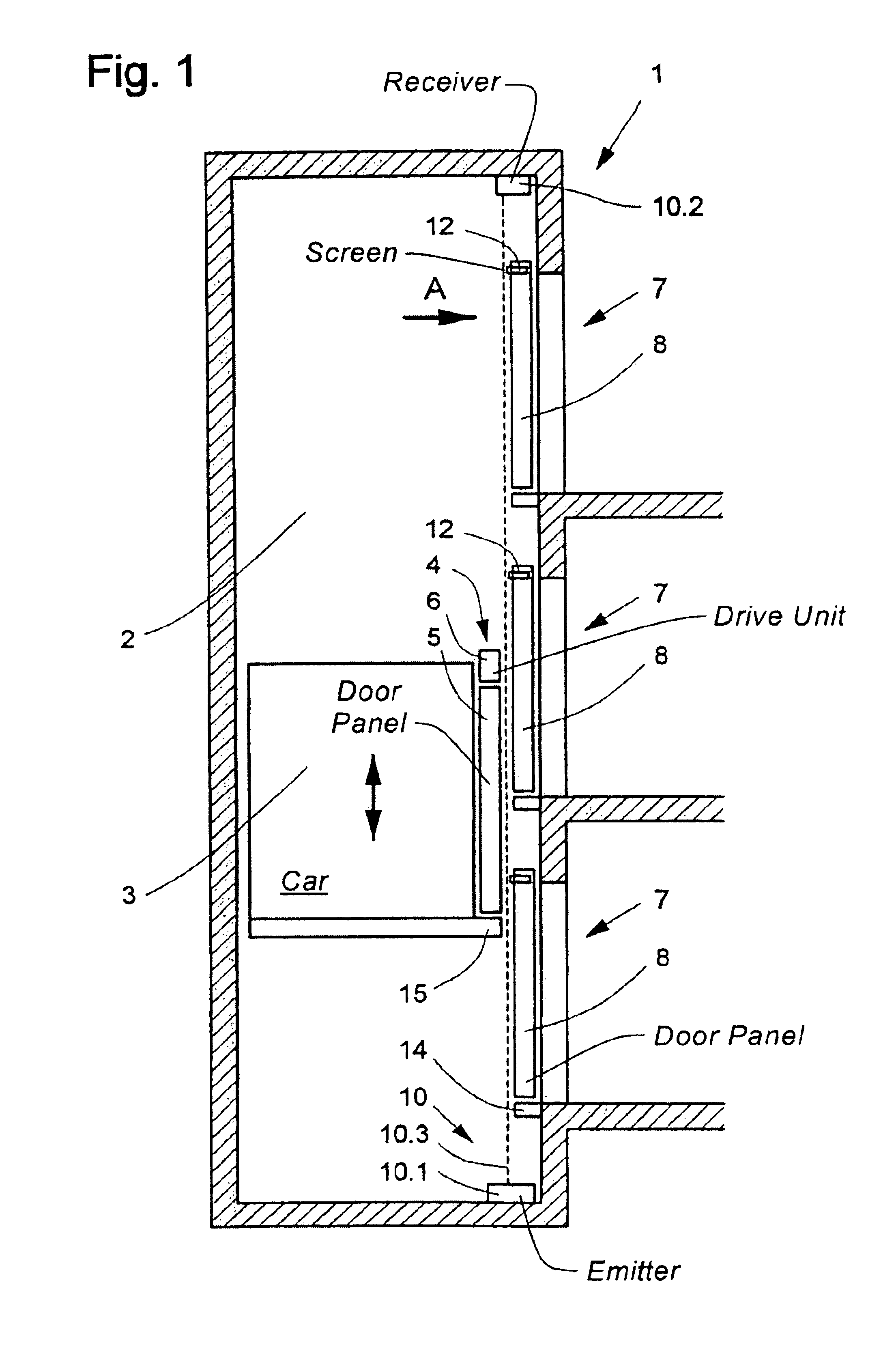
[0043]An elevator installation 1 with an elevator shaft 2 and an elevator car 3 is illustrated schematically in FIG. 1. The elevator car 3 is equipped with a car door 4, which has two car door panels 5 which, for opening and closing, are horizontally displaced by a door drive unit 6 mounted at the elevator car. The elevator shaft 2 includes three shaft doors 7, which each have two shaft door panels 8. The opening and closing of the shaft door 7 is effected by horizontal movement of the shaft door panels 8 thereof when the elevator car 3 is disposed at the corresponding floor, wherein the drive force for this horizontal movement is transmitted by means of a door actuating mechanism from the car door panels 5 to the shaft door panels 8.

[0044]In the closed state, the shaft door panels 8 are locked by means of a shaft door lock—not shown here—with a stationary part of the shaft doors. An emitter installed in the region of the shaft pit and near the shaft wall containing the shaft doors ...


PUM


Abstract

A method for monitoring shaft doors of a elevator installation uses at least one contactlessly acting shaft door monitoring sensor to emit a beam of electromagnetic waves, wherein at least during specific detection phases the beam extends over several floors and is detected by a receiver. The beam is influenced by a shaft door panel not being completely closed and/or a shaft door lock not being disposed in the locking setting such that a disturbance signal is generated to the elevator control.

Description

BACKGROUND OF THE INVENTION[0001]The present invention relates generally to a method for monitoring shaft doors of an elevator installation.[0002]Elevator installations usually include shaft doors that in closed state separate, on each floor, the elevator shaft from the adjoining spaces. In the case of elevator installations of the conventional kind, the load receiving means (elevator car) is also equipped with a door, which is termed a car door and which moves together with the elevator car from floor to floor. The opening and closing of the car doors is normally effected, during stopping of the elevator car at a floor, by a car door drive controlled by an elevator control. In that case the car door panels are coupled with the respectively corresponding shaft door panels so that the shaft door panels accompany the movement of the car door panels.[0003]For the safety of users of the elevator installation and passers-by in the building it is of great importance that a shaft door shou...

Claims


Application Information

Patent Timeline
Patent Type & Authority Patents(United States)
IPC IPC(8): B66B13/14B66B13/22
CPCB66B13/143
Inventor ANGST, PHILIPPBAUMGARTNER, URS
Owner INVENTIO AG
Why Eureka
Try Eureka