Rotor and exciter ring

a technology of exciter ring and rotor, which is applied in the direction of braking disc, braking system, aircraft braking arrangement, etc., can solve the problem of thermal expansion of the rotor

Active Publication Date: 2005-09-20
PERFORMANCE FRICTION
View PDF10 Cites 34 Cited by
  • Summary
  • Abstract
  • Description
  • Claims
  • Application Information

AI Technical Summary

Benefits of technology

[0003]An advantage of the present invention resides in structure that allows for independent thermal expansion of the rotor and an exciter ring and as a result information obtained with respect to rotation of the rotor is not effected by the generation of thermal energy between the rotor and friction members.
[0004]According to this invention, a rotor assembly for a vehicle is mounted on a hub that is retained on an axle of a vehicle. The rotor assembly is distinguished by a radial disc that is offset from a mounting flange that is fixed to the hub by a cylindrical body and an exciter ring through which a sensor detects rotation of the radial disc with respect to the axle. The radial disc has a first surface that functions as a first friction face and a second surface that functions as a second friction face for first and second friction members. The first and second friction members respectively engage the first and second surfaces to attenuate the rotation of the radial disc during a brake application. The first and second friction members on engagement with the first and second friction faces generate thermal energy that is carried from the radial disc toward the mounting flange by way of the cylindrical body of the rotor. The radial disc reacts to a predetermined thermal energy level by being distorted from perpendicular alignment to non-perpendicular alignment with respect to the hub. The exciter ring is characterized by a cylindrical member having a first end that is concentrically located within the cylindrical body of the rotor to define a gap between a face on an outwardly extending flange on a second end thereof and the radial disc. The outwardly extending flange has a plurality of reluctance sections located thereon that are aligned with the sensor. The sensor reacts to movement of the reluctance sections to provide an electronic control unit with information relating to the rotation of the radial disc, The gap allows the radial disc to move independently with respect to the outwardly extending flange such that the plurality of reluctance sections remain aligned with the sensor whenever the radial disc changes from perpendicular to non-perpendicular alignment with respect to the hub.
[0005]An advantage of this invention resides in structure that allows a rotor disc to independently move in response to thermal expansive changes while an exciter ring remains in a desired alignment with respect to a sensor that provides an electronic control unit with information relating to the rotation of the rotor.
[0006]A further advantage of this invention resides in an attachment of a rotor with a hub whereby the retention of an exciter ring with respect to a rotor is not skewed by deflection of the rotor resulting from thermal expansion.
[0007]A still further advantage of this invention resides in an attachment arrangement for an exciter ring to a rotor whereby the exciter ring is retained during a thermal expansion event of the rotor and not pushed toward a sensor.

Problems solved by technology

An integral exciter ring functions in an adequate manner under most operational conditions however under an extreme brake duty cycle during which friction members sequentially engage the rotor for a long period of time without a sufficient time to allow the rotor to cool between periods of engagement, the rotor will experience thermally expansion.

Method used


Image

  • Rotor and exciter ring
  • Rotor and exciter ring
  • Rotor and exciter ring

Examples


Embodiment Construction

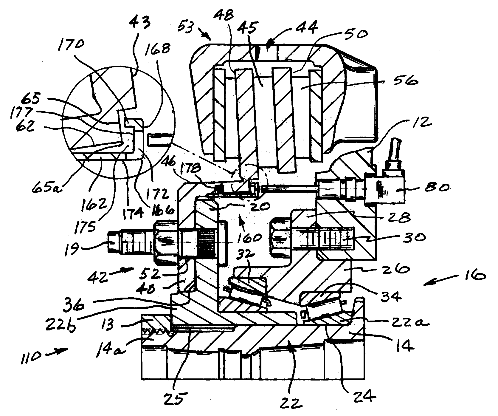
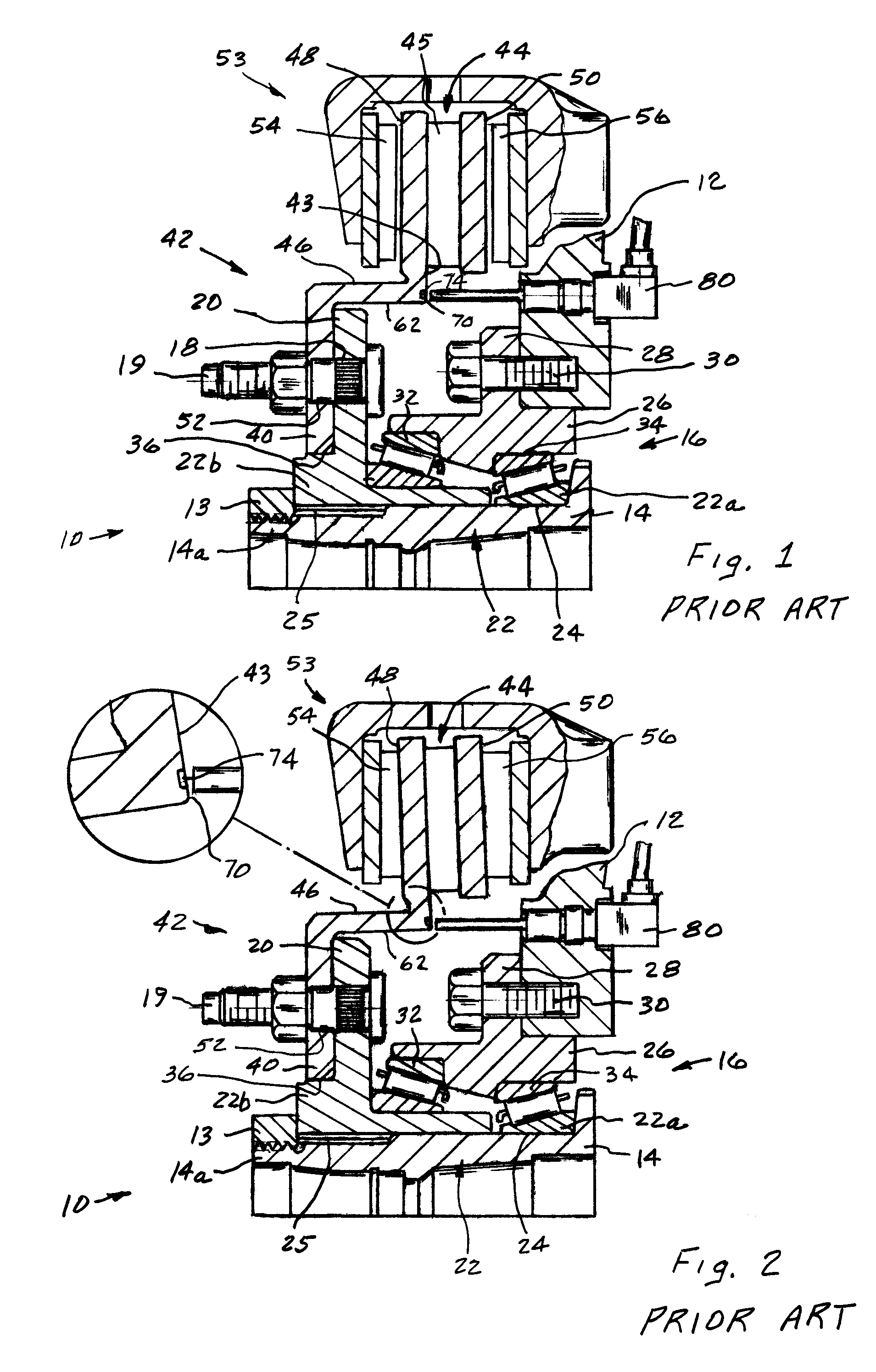
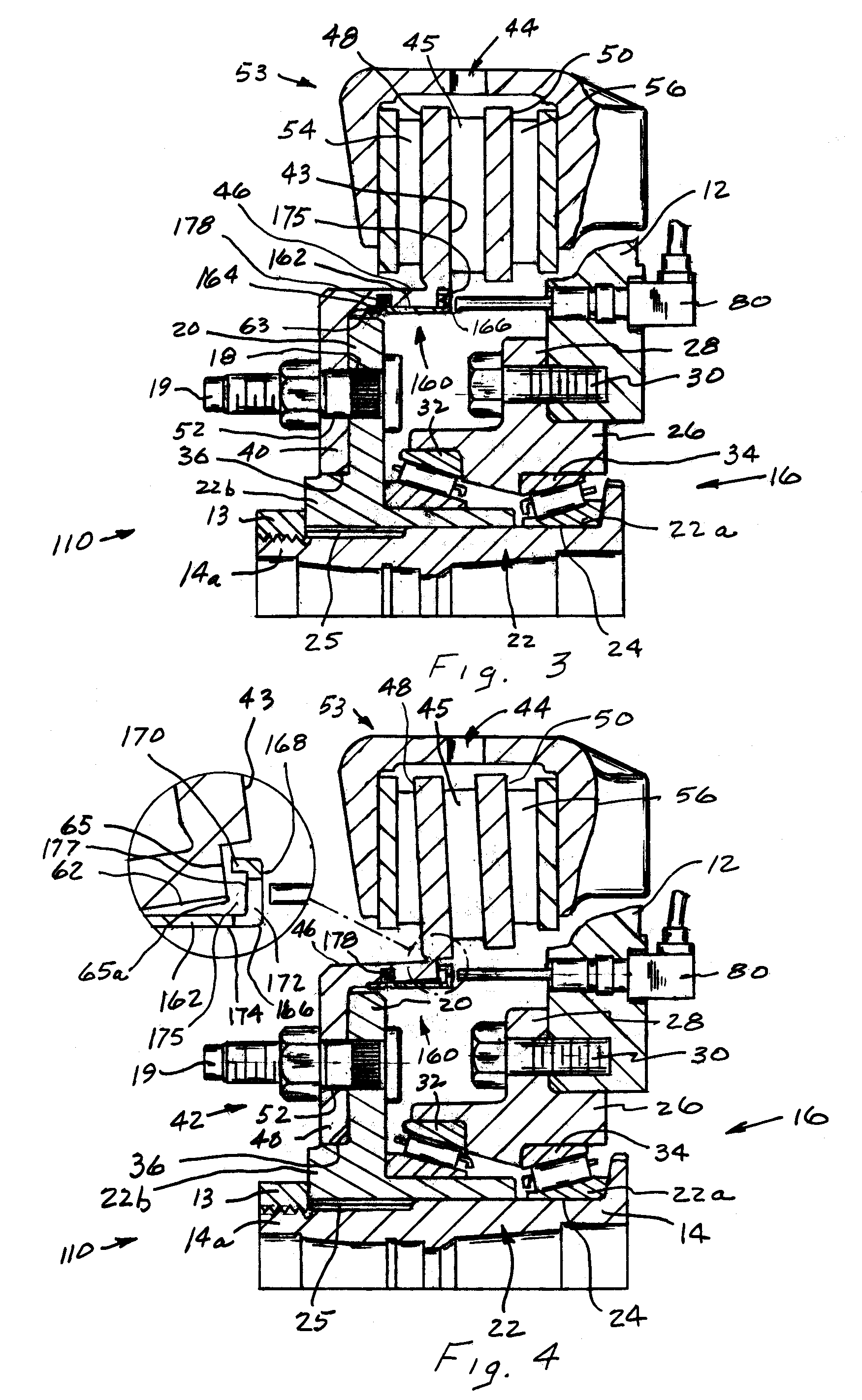
[0018]In the description that follows, components of the disc brake in the various embodiments that are identical may be identified by a same number or the same number plus whenever necessary to better describe a functional relationship with another component.

[0019]The present invention is designed to be incorporated in a corner assembly 10 and may be of a type such as disclosed in U.S. Pat. No. 5,984,422 or 6,718,634, wherein a hub 14 and bearing 16 are retained in a knuckle 12 as illustrated in FIG. 1. The bearing 16 includes an inner race 22 with a flange 20 that has a plurality of openings 18 (only one is shown) for receiving a corresponding plurality of studs 19 through which a rotor 42 and ultimately a rim of a wheel are attached to an axle of the vehicle. The inner race 22 of bearing 16 is located on a mounting surface 24 of the hub 14 and separated from an outer race 26 by a plurality of rollers 32,34 (only two are shown) that are located between the inner race 22 and outer ...


PUM


Abstract

A rotor assembly with a cylindrical body having a radial disc that is perpendicularly aligned with a hub of a vehicle and an exciter ring through which a sensor detects rotation of the radial disc. The exciter ring is concentrically installed within the cylindrical body to define a gap between a flange thereon and the radial disc. Reluctance sections on the flange are axially aligned with the sensor to generate a signal indicative of rotation. Friction members engage the radial disc and generate thermal energy that is conducted a mounting flange. Thermal energy level may cause the rotor assembly to expand and change the alignment of the radial disc from perpendicular and non-perpendicular with respect to the hub. The gap allows the radial disc and exciter ring to independently move such that the reluctance sections remain axially aligned with the sensor and sensed information is an accurate indication of rotation.

Description

BACKGROUND OF INVENTION[0001]This invention relates to a rotor that is mounted on a hub that is retained on an axle with an exciter ring attached to the rotor wherein the exciter ring remains substantially concentric to the axle whenever the rotor experiences thermal expansive changes resulting from a brake application such that information detected by a sensor regarding the rotative movement of the rotor is not effected by changes in a perpendicular relationship between the rotor and the hub.[0002]It is common to provide a vehicle with an electronic control that includes means to detect rotation of the wheels. Information relating to the rotation of the wheels is most often used to effect a brake application of a wheel when information is sensed that may adversely effect the safety or operation of a vehicle. Some of the information is often obtained from an electronic device that detects movement of a rotor by sensing reluctance changes in an exciter ring attached to a hub, as illu...

Claims


Application Information

Patent Timeline
Patent Type & Authority Patents(United States)
IPC IPC(8): B60T1/06B60T1/00B60T8/32F16D65/12
CPCB60T8/329F16D65/12
Inventor YUHAS, DAVID M.
Owner PERFORMANCE FRICTION
Why Eureka
Try Eureka