Pressure hitch

a technology of pressure hitch and spherical plate, which is applied in the direction of lifting devices, soil shifting machines/dredgers, transportation and packaging, etc., can solve the problems of difficult and even clumsy, inconvenient operation, and inability to use the same size and style of design for ball and socket hitching components

Active Publication Date: 2005-09-20
GERRES WELDING & MFG
View PDF12 Cites 5 Cited by
  • Summary
  • Abstract
  • Description
  • Claims
  • Application Information

AI Technical Summary

Benefits of technology

[0009]Ideally, the rubber pressure stub resists compression in excess of 20 percent in the vertical direction. It preferably is of synthetic rubber, although natural rubber is useful. The most ideal synthetic rubber is in the neoprene family. The rubber pressure stub should have a transverse width in all directions transverse to its vertical movement of at least about ⅜ inch. The greatest transverse width usually will not exceed about two inches. While a greater transverse width (e.g., diameter) for the rubber pressure stub can be useful, it is normally unnecessary, and thus the added expense of greater width can be avoided. The length of the rubber pressure stub in the vertical direction (i.e., the longitudinal or axis direction of the vertical movement of the ram) can be relatively short (e.g., as little as ⅛ inch) but adequate to cushion the contact with the upper outer surface of the cup-shaped socket. Ideally, the length of the rubber stub will be at least ¼ inch and can be as great as several inches (e.g., usually not over about two inches), but a cushion length greater than about one inch is generally unnecessary.
[0011]The most ideal hitching assembly for a towing vehicle is one where the basic ball hitch is on a draw bar extending outward from one face of a vertically orientable base plate having opposite face sides, and where the vertically orientable hydraulically operated ram assembly is one having a hydraulic cylinder end equipped with a terminal structure by which the ram assembly is vertically suspended from the elevated outer end of a boom rigidly united at its inner end to the one face side of the base plate from which the draw bar extends. A mid-level bracing structure for holding the ram assembly in stable condition for hydraulic movement of the rubber pressure stub vertically toward and away from the basic ball hitch is desirable.
[0012]An ideal towing vehicle for the invention is a front-end loader, especially one equipped with a toe-heel attachment carrier to which the vertically orientable base plate having opposite face sides as above-mentioned can be mounted. This approach permits great convenience for tilting the towing hitch arrangement as well as for horizontal and vertical movement of it relative to an inverted socket on the tongue of a towable vehicle. As a consequence, the basic ball hitch of the towing vehicle can easily be oriented under (and even into) the inverted cup-shaped socket on the tongue of the towable vehicle. Tongues of towable vehicles are nowadays usually equipped with a depending foot to keep them above ground level a short distance so as to permit easy movement of a basic ball hitch on a towing vehicle into the inverted socket. Thereafter, vertical movement of the rubber pressure stub of the hydraulically operated ram assembly into a pressed condition against the upper outer surface of the inverted cup-shaped socket is easily accomplished to hold the cup-shaped socket in coupled relationship on the basic ball hitch without need to tighten the cup-shaped socket to form a grip about the basic ball hitch.

Problems solved by technology

That approach is not useful where a ball hitch arrangement is on the towing vehicle and an inverted cup-shaped socket hitch arrangement is on the towable vehicle.
The chain on the tractor is wiggled under the hook on the implement to align the socket of the implement over the ball hitch on the draw bar of a tractor—a result that can be difficult and even clumsy to accomplish.
Unfortunately, ball and socket hitching components are not routinely of the same matching size and style of design.
The variations have militated against dreams of universal ball and socket cab-controlled hitching and unhitching, and have frustrated operators into the practice of departing from the cab of a towing vehicle to attend to tightening each special cup-shaped socket into a gripping relationship on a suitable previously selected ball on the towing vehicle.

Method used


Image

  • Pressure hitch
  • Pressure hitch
  • Pressure hitch

Examples


Embodiment Construction

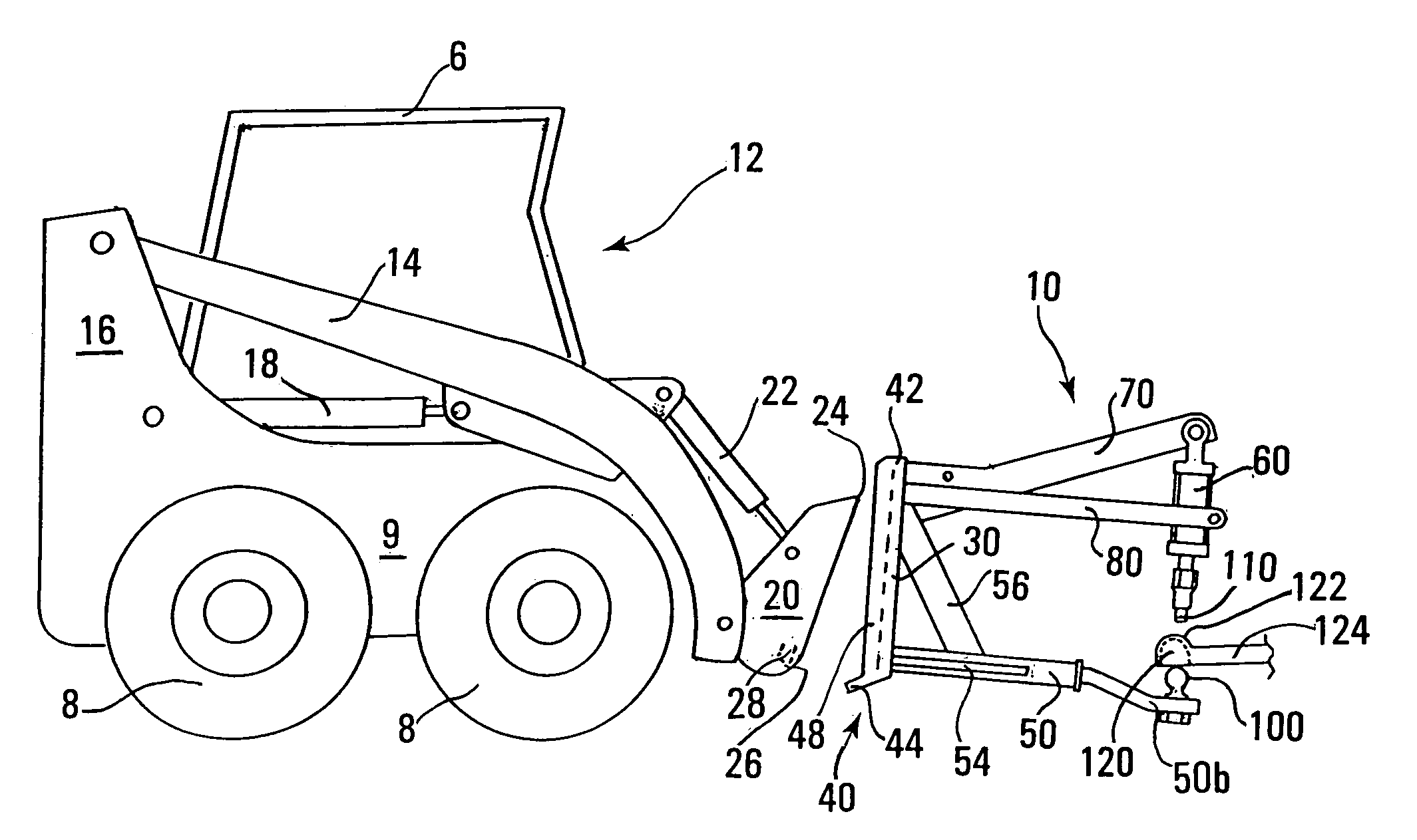
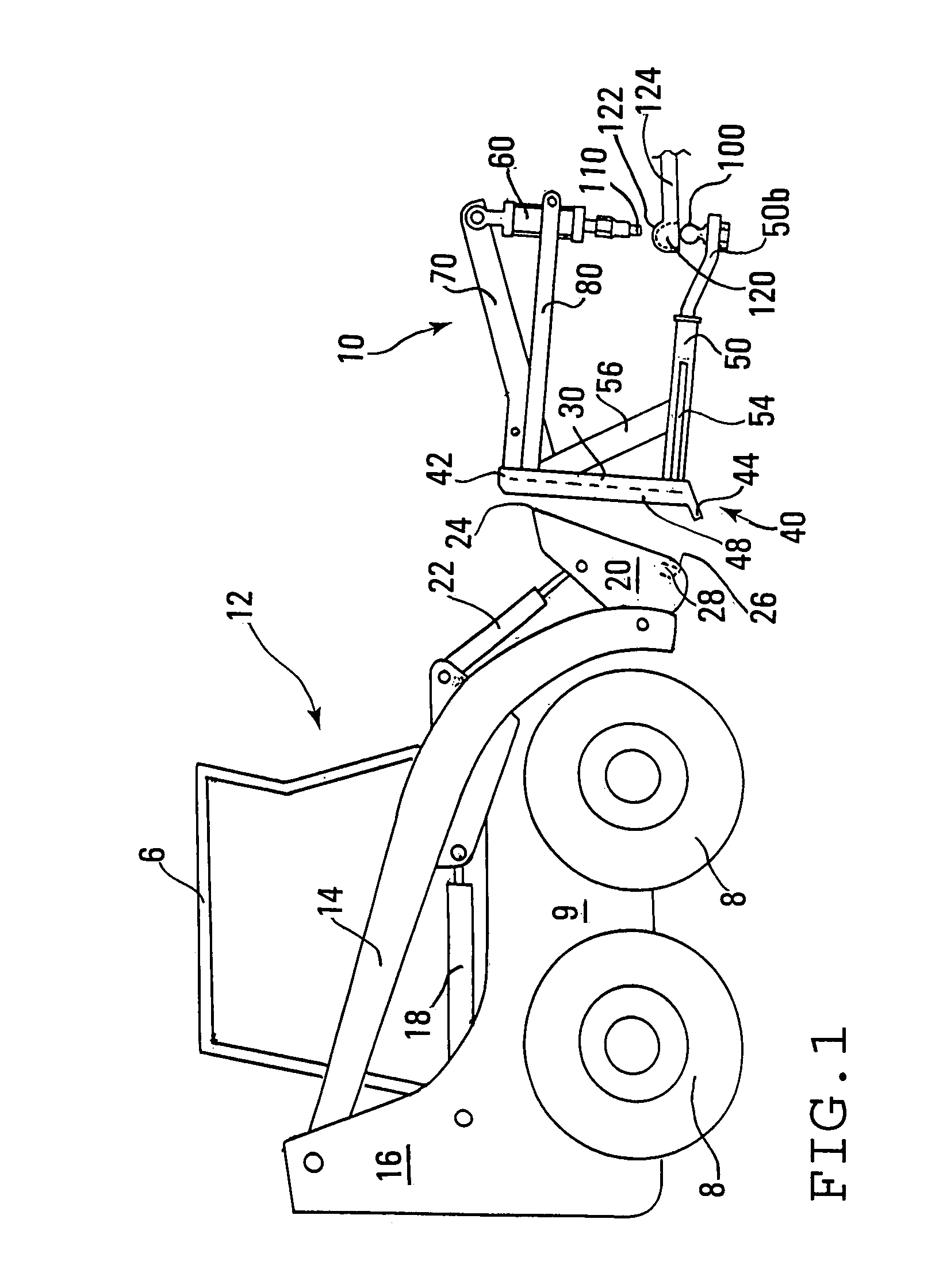
[0018]Referring particularly to FIGS. 1, 2, and 3, the new hitch assembly of the invention permits an operator to pressure-couple a towable vehicle 124 to a towing vehicle 12 while the operator remains in the cab 6 of the towing vehicle. The towable vehicle 124 is illustrated in the drawings solely by the tongue of it. Greater detail for the towable vehicle is believed unnecessary. The variety of possibilities for towable vehicles is almost endless.

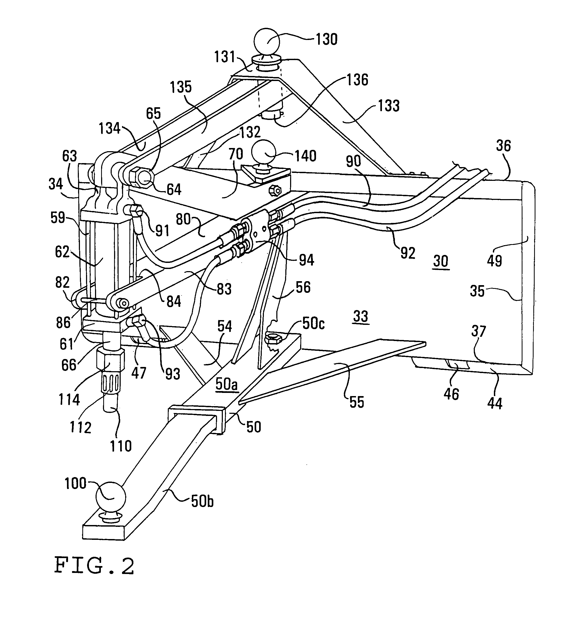
[0019]The towing vehicle has a towing hitch arrangement 10 that requires a ball hitch 100 (herein referred to as the basic ball hitch) and a vertically orientable hydraulically operated ram assembly 60 having a hydraulic ram equipped with a rubber pressure stub 110 at its lowermost end in an orientation above the basic ball hitch for hydraulic movement of the rubber pressure stub vertically toward and away from the basic ball hitch.

[0020]The towable hitch arrangement consists essentially of an inverted cup-shaped socket 120 for coupling o...


PUM


Abstract

The pressure hitch is operable from the cab of a towing vehicle. The towing vehicle is equipped with a basic ball hitch and a vertically orientable hydraulically operated ram having a rubber pressure stub at its lowermost end in an orientation above the basic ball hitch. The towed vehicle has an inverted cup-shaped socket for coupling (without need for grip tightening) on the basic ball hitch. The ram's rubber pressure stub is vertically movable for pressing against the upper outer surface of the socket and is the sole structure for holding the socket and basic ball hitch together during towing operations. The ideal towing vehicle is a front end loader.

Description

FIELD OF THE INVENTION[0001]This invention relates to a pressure hitch operable from the cab of a towing vehicle, and more particularly to the use of remotely controlled pressure to hold hitch components between a towing and towed vehicle against separation.BACKGROUND OF THE INVENTION[0002]Rapid hitching and unhitching of towable vehicles from towing vehicles with maximum convenience (i.e., minimal labor) has become more and more critical as towable vehicles have proliferated and the operators / proprietors of businesses dealing with towable vehicles for rent or sale have recognized that attractive aligned display of towable vehicles has a salutary effect in attracting customers. Rapid hitching and unhitching with maximum convenience also is important for businesses having a multitude of different towable implements and for operators who have every desire to avoid getting in and out of the cab of a towing vehicle to secure and release each hitch connection. In short, rapid hitching an...

Claims


Application Information

Patent Timeline
Patent Type & Authority Patents(United States)
IPC IPC(8): B60D1/00B60D1/04B60D1/02B60D1/06B60D1/07
CPCB60D1/02B60D1/065B60D1/07B60D1/583
Inventor GERRES, RONALD F.GERRES, STEVEN M.
Owner GERRES WELDING & MFG
Why Eureka
Try Eureka