Mobile bearing unicompartmental knee

a mobile bearing and uni-compartmental technology, applied in knee joints, knees, prostheses, etc., can solve the problems of few, if any, designs for mobile bearing uni knees

Inactive Publication Date: 2005-09-20
ZIMMER TECH INC
View PDF7 Cites 106 Cited by
  • Summary
  • Abstract
  • Description
  • Claims
  • Application Information

AI Technical Summary

Benefits of technology

[0008]An advantage of the present invention is that it provides a mobile bearing prosthetic knee useful in with a partial knee arthroplasty. Other advantag

Problems solved by technology

However, as uni prosthetic knee joints are less well known than their total knee

Method used


Image

  • Mobile bearing unicompartmental knee
  • Mobile bearing unicompartmental knee
  • Mobile bearing unicompartmental knee

Examples


first embodiment

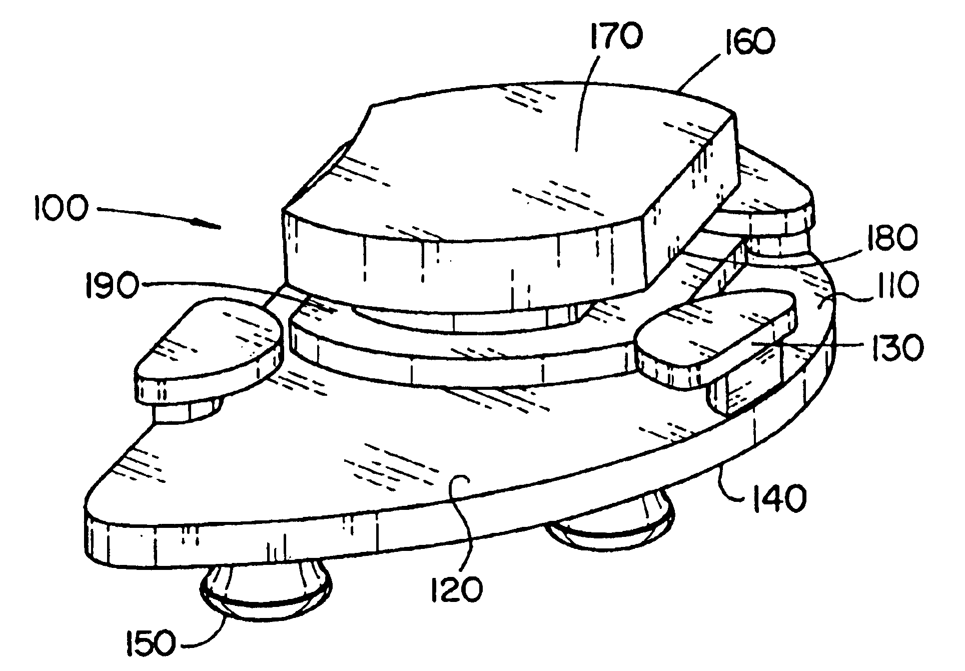
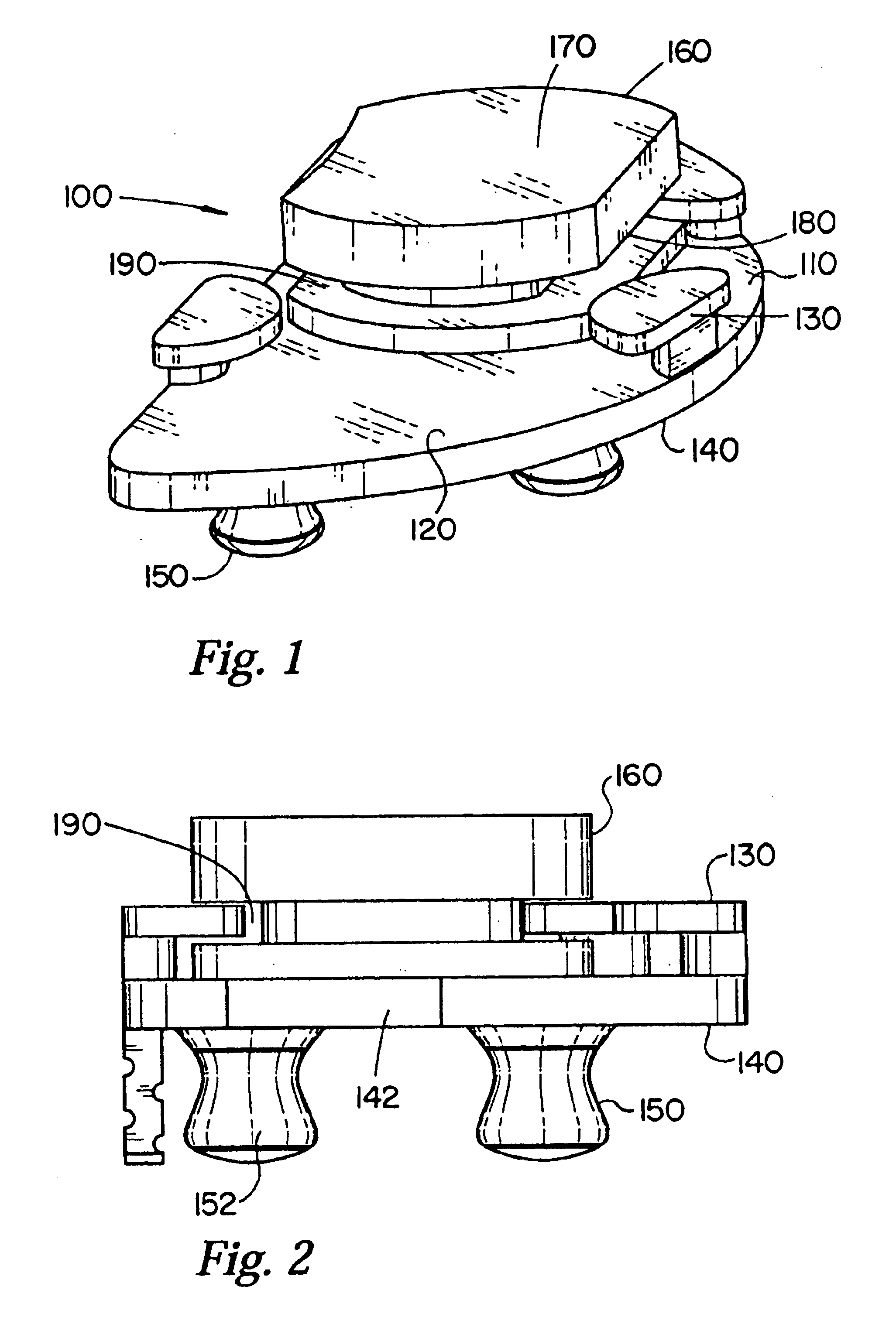
[0020]In FIG. 1, there is shown a perspective view of a prosthetic uni knee implant 100 according to the present invention comprising: tibial tray 110 and bearing component 160. Implant 100 is insertable into the joint space within a single compartment of a human knee in order to replace bone and tissue lost to trauma or disease. It is to be appreciated that an embodiment of the present invention is useful for medial partial knee arthroplasty, lateral partial knee arthroplasty, or total knee arthroplasty.

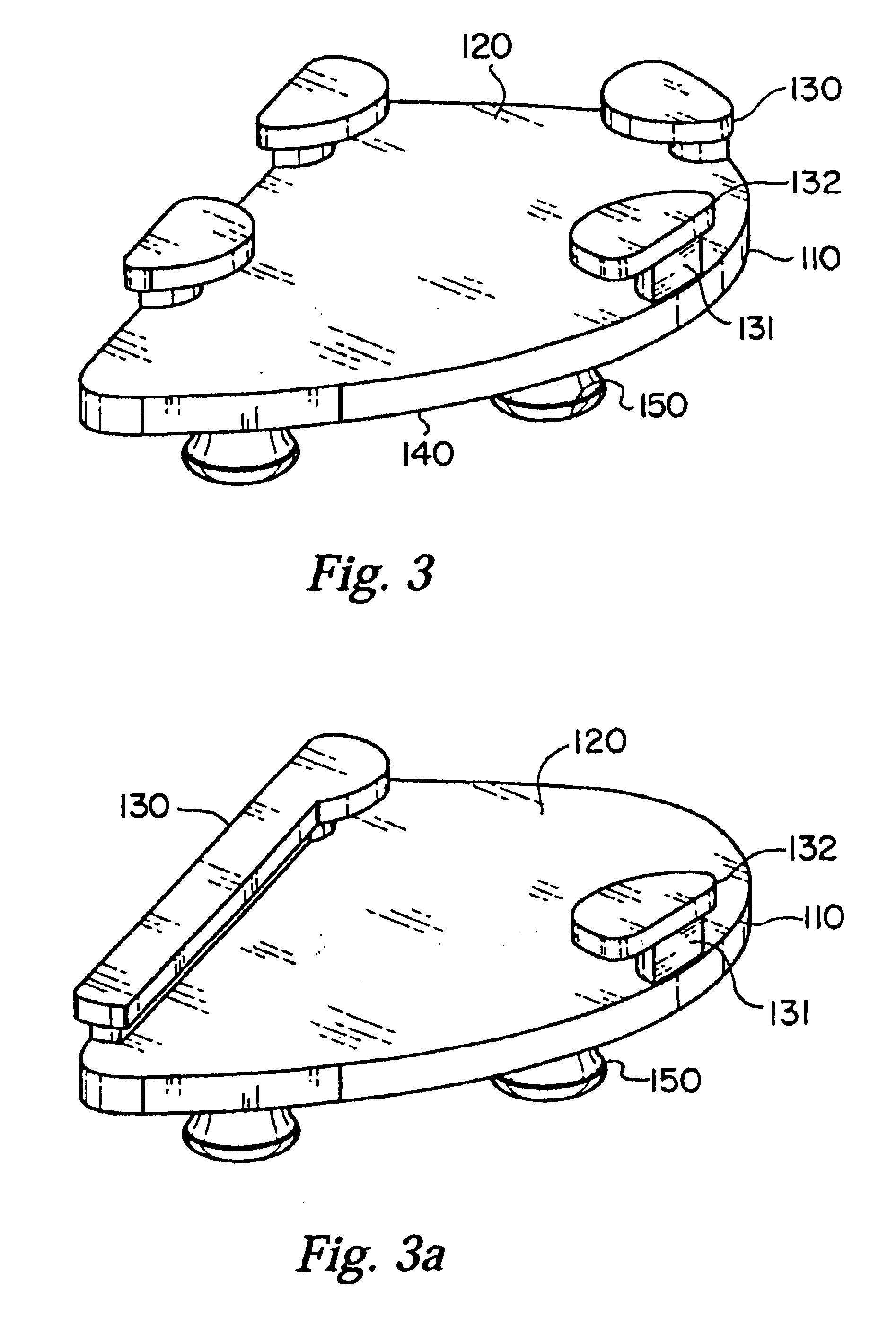
[0021]Referring now to FIG. 3, tibial tray 110 of the present invention comprises: a superior surface 120, at least two tabs 130, and inferior surface 140, and pegs 150 for attaching tray 110 to a human tibia. Tibial tray 110 is appropriately sized to fit within the joint space created during a knee arthroplasty. Tibial tray 110 may further comprise any biocompatible material having the requisite mechanical properties necessary for tray 110 to function as a tibial implant, including...

second embodiment

[0028]FIGS. 5-7 show implant 200 according to the present invention, wherein the implant comprises femoral component 210, bearing component 260 and tibial tray 290.

[0029]Referring now to FIG. 5, specifically femoral component 210 comprises a bone contacting surface 220 for engaging a surgically prepared distal femur. Bone contacting surface 220 generally includes a plurality of intersecting planes and means of affixing femoral component 210 to the prepared distal femur. These means may include press fitting, screws, bone ingrowth materials, posts or a combination of the same.

[0030]Referring now to FIGS. 5 and 6, femoral component 210 further comprises articulating surface 230 disposed opposite bone contacting surface 220. Articulating surface 230 is generally arcuated such that is can rotate and translate relative to a bearing component, such as the one described herein below.

[0031]Referring now to FIG. 7, femoral component 210 further comprises medial and lateral edges and a rail 2...


PUM


Abstract

An orthopedic knee component for implanting within a single compartment of a human knee includes, in a first embodiment a tibial tray having a superior surface having a plurality of tabs disposed along an exterior edge thereof, a bearing component having a superior surface adapted to articularly engage a femoral knee prosthesis and a circumferential groove disposed therearound with which the tabs of the tibial tray cooperatively engage such that the bearing component is movable relative to the tibial tray. In a second embodiment, an orthopedic knee component for implanting within a single compartment of a human knee includes: a tibial tray in supporting engagement with a bearing component, wherein the bearing component includes a superior surface adapted to articularly engage a femoral knee prosthesis and a pair of slots disposed along the superior surface of the bearing component, the femoral component having a pair of rails extending from the articulating surface thereof such that the rails can slidingly engage the slots, and such that the bearing component is movable relative to the tibial tray.

Description

BACKGROUND OF THE INVENTION[0001]1. Field of the Invention[0002]The present invention relates generally to prosthetic knee implants of the type commonly referred to as “mobile bearing.” More specifically the invention relates to mobile bearing knees for use in unicompartmental (“uni”) knee prostheses.[0003]2. Description of the Related Art[0004]Prosthetic knee implants having a bearing component that is movable relative to a fixed tibial tray during flexion and extension of a person's knee joint are known as mobile bearing knees and will be referred to as such throughout this document. Mobile bearing knees generally consist of a tibial tray affixed to a prepared proximal tibia and a bearing component which typically comprises ultra high molecular weight polyethylene (“UHMWPE”). The bearing component is adapted to allow a femoral component to articulate against the same. Often, there exists a mechanism or a plurality of mechanisms to restrict or limit movement of the bearing componen...

Claims


Application Information

Patent Timeline
IPC IPC(8): A61F2/38A61L27/00A61L27/06A61L27/04A61L27/14
CPCA61F2/3868A61F2002/3895
Inventor SANFORD, ADAMFARLING, TOBYWEBSTER, VINCENTHODOREK, ROBERTLAZAR, SCOTTSTEFFENSMEIER, SCOTT J.
Owner ZIMMER TECH INC
Why Eureka
Try Eureka