Electrochemical polymer electrolyte membrane cell stacks and manufacturing methods thereof

a technology of polymer electrolyte membrane and stack, which is applied in the direction of cell components, final product manufacturing, sustainable manufacturing/processing, etc., can solve the problems of high cost of fuel cells when compared to conventional power generation technology, deterred their potentially widespread use, and high cost of fabricating and assembling fuel cells, so as to achieve the effect of simplifying the assembly of the finished fuel cell stack

Inactive Publication Date: 2005-09-20
SILICON VALLEY BANK
View PDF21 Cites 26 Cited by
  • Summary
  • Abstract
  • Description
  • Claims
  • Application Information

AI Technical Summary

Benefits of technology

[0043]In one embodiment of the present invention, assembly of the finished fuel cell stack is further simplified by interposing the fuel cell stack assembly between two joined housin...

Problems solved by technology

However, the high cost of fuel cells when compared to conventional power generation technology has deterred their potentially widespread use.
Costs of fabricating and assembling fuel cells can be significant, due to the materials and labor involved, and as much as 85% of a fuel cell's price can be attributed to manufacturing costs.
These processes are labor intensive and not conducive to high volume manufacturing and add to the high cost of fuel cells.
The variability of these processes also results in poor manufacturing yield and device reliability.
Fuel cell stacks range in design depending upon power output, cooling, and other technical requirements, but may utilize a multitude of MEAs, seals, flow fields, and separator plates, in intricate assemblies that result in manufacturing difficulties and further increase fuel cell costs.
These current means of applying compression add even more components and complexity to the stack an...

Method used


Image

  • Electrochemical polymer electrolyte membrane cell stacks and manufacturing methods thereof
  • Electrochemical polymer electrolyte membrane cell stacks and manufacturing methods thereof
  • Electrochemical polymer electrolyte membrane cell stacks and manufacturing methods thereof

Examples


Embodiment Construction

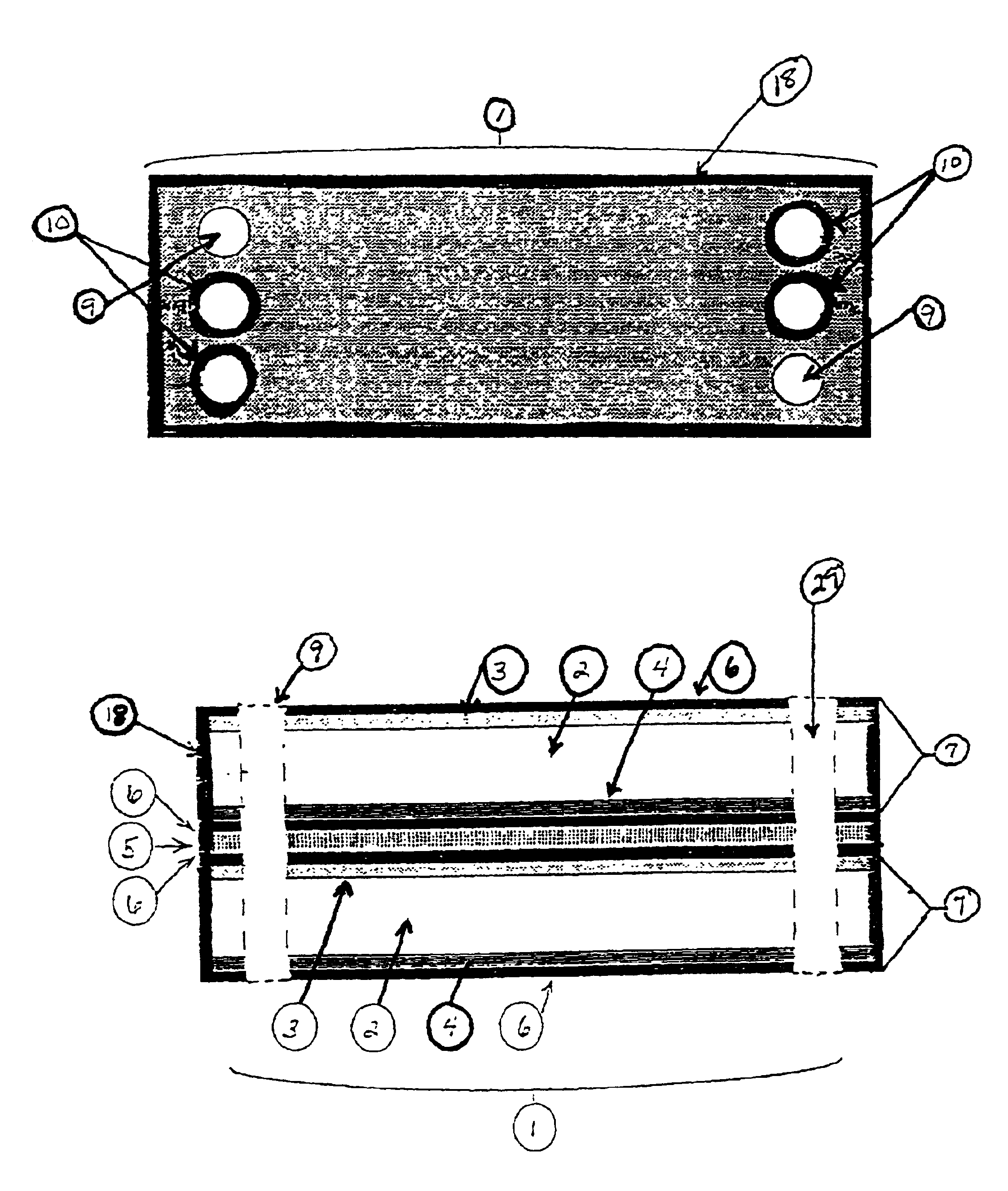
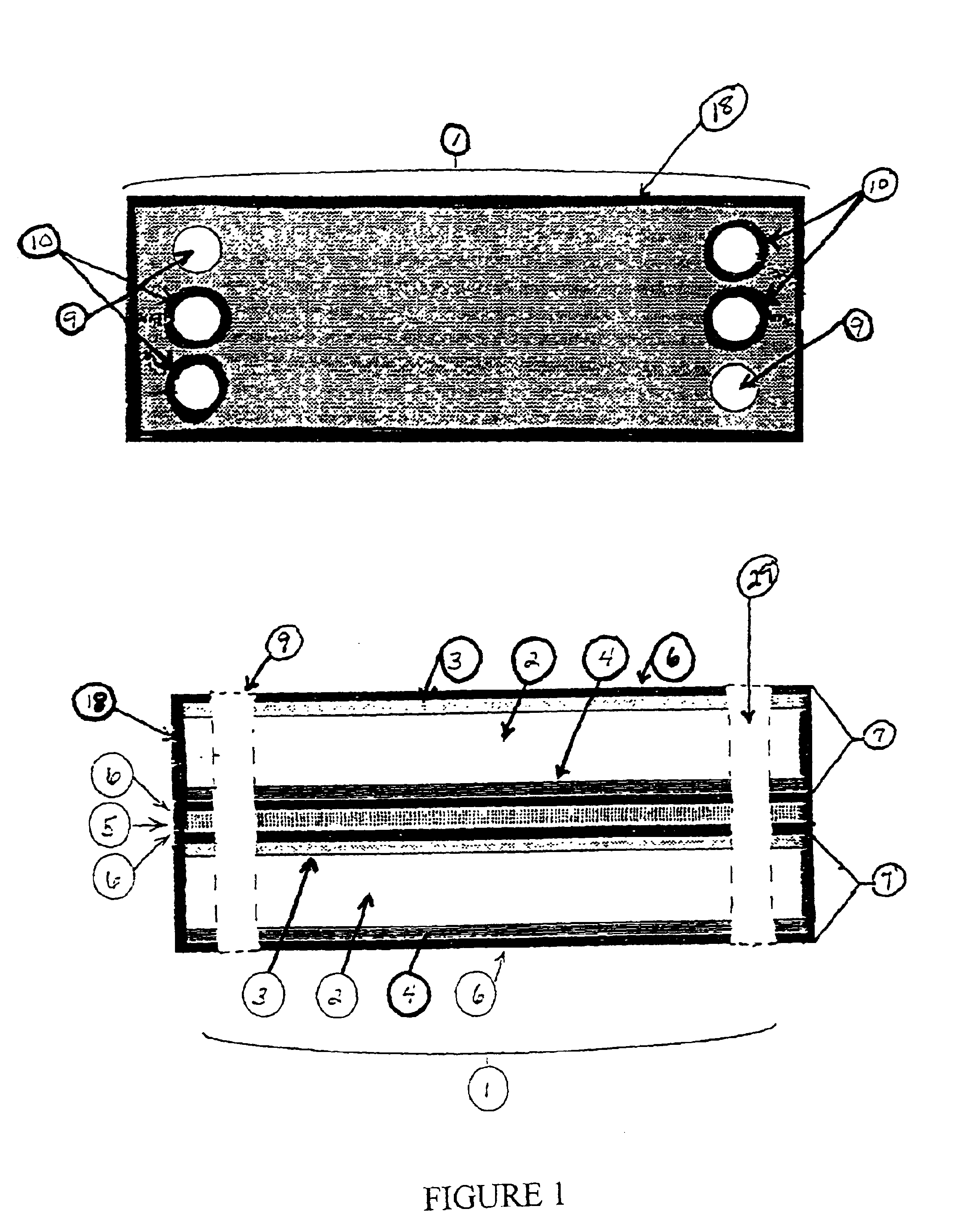
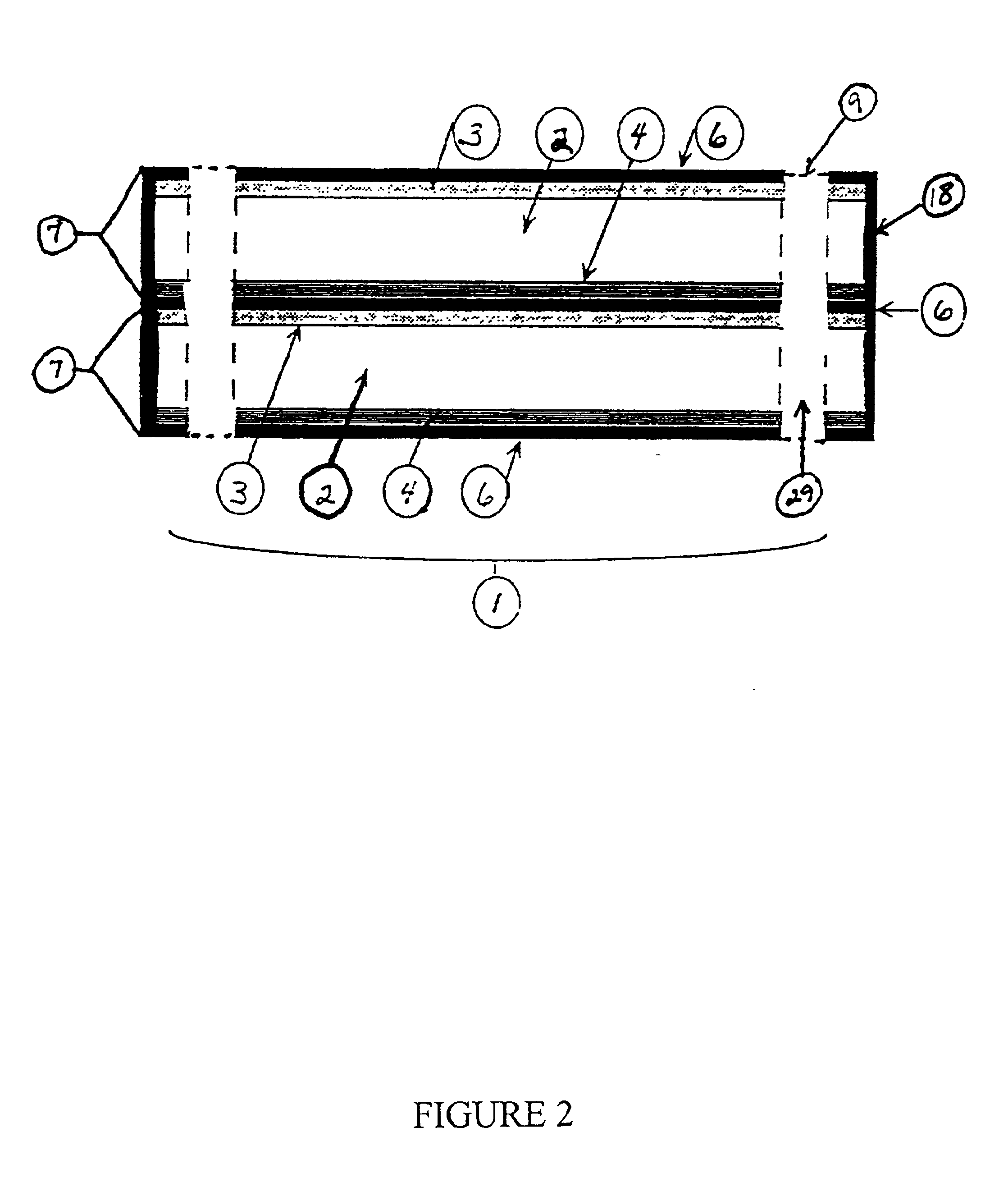
[0055]Referring now to FIG. 1, a fuel cell cassette 1 of the present invention is shown. The fuel cell cassette 1 shown comprises two unit cells 7, each unit cell having a separator plate 6, a fuel flow field 3, a MEA 2, and an oxidant flow field 4. A coolant flow field 5 is sandwiched between the two unit cells 7, with the addition of separator plates 6, to provide cooling capability to the fuel cell cassette. However, it should be understood that the fuel cell cassette 1 is shown in its present configuration to facilitate the illustration of the present invention. As will be apparent to those skilled in the art, an individual fuel cell cassette may embody various assemblies of MEAs, flow field plates and separator plates, as well as other fuel cell components to form unit cells within the fuel cell cassette and also that each such unit cell may be repeated or combined with different unit cells, dependent upon the power output, humidification and / or cooling requirements for the c...


PUM

PropertyMeasurementUnit
Thermosettingaaaaaaaaaa

Abstract

An improved electrochemical polymer electrolyte membrane cell stack is provided that includes one or more individual fuel cell cassettes, each fuel cell cassette having at least one membrane electrode assembly, fuel flow field and oxidant flow field. Within each fuel cell cassette, each membrane electrode assembly has at least one manifold opening for the passage of reactant manifolds through the cassette, all of which are bonded about the perimeter by a sealant, and each flow field has at least one manifold opening and any manifold openings on the flow fields which do not correspond to a manifold providing reactant for distribution to such flow field is bonded about its perimeter by a sealant. Each fuel cell cassette may also contain other typical components of a electrochemical polymer electrolyte membrane cell stack, such as separator plates or coolant flow fields, which also have manifold openings which may or may not be bonded about the perimeter. The membrane electrode assembly, flow fields, and other components are encapsulated along the peripheral edges by a resin such that the entire periphery of the fuel cell cassette is encapsulated by the resin.

Description

[0001]This application claims the benefit of Provisional Application No. 60 / 253,199, filed Nov. 27, 2000.TECHNICAL FIELD[0002]This invention relates to electrochemical polymer electrolyte membrane (“PEM”) cells and stacks thereof, and more particularly, to PEM fuel cell stacks. The present invention also describes novel processes for producing these PEM fuel cell stacks.BACKGROUND ART[0003]Electrochemical PEM cells, and particularly, PEM fuel cells are well known. PEM fuel cells convert chemical energy to electrical power with virtually no environmental emissions and differ from a battery in that energy is not stored, but derived from supplied fuel. Therefore, a fuel cell is not tied to a charge / discharge cycle and can maintain a specific power output as long as fuel is continuously supplied. The large investments into fuel cell research and commercialization indicate the technology has considerable potential in the marketplace. However, the high cost of fuel cells when compared to ...

Claims


Application Information

Patent Timeline
IPC IPC(8): H01M8/02H01M8/24H01M8/10
CPCH01M8/0271H01M8/0284H01M8/0286H01M8/0297H01M8/1002H01M8/242H01M8/2475H01M8/248H01M8/249Y02E60/521H01M8/1007Y02P70/50Y02E60/50H01M8/241H01M8/0258H01M8/0267H01M8/2483
Inventor OSENAR, PAULFORMATO, RICHARD M.HERCZEG, ATTILA E.ENAYETULLAH, MOHAMMAD
Owner SILICON VALLEY BANK
Why Eureka
Try Eureka