Polyphase claw pole structures for an electrical machine

a technology of polyphase electrical machinery and claw poles, which is applied in the direction of dynamo-electric machines, electrical apparatus, magnetic circuits, etc., can solve the problems of less heat transfer efficiency, difficult assembly of these claw poles to the stack, and increased magnetic losses, so as to improve the production process, increase the effect of magnetic losses and reduce the cos

Inactive Publication Date: 2005-09-20
QUEBEC METAL POWDERS
View PDF9 Cites 52 Cited by
  • Summary
  • Abstract
  • Description
  • Claims
  • Application Information

AI Technical Summary

Benefits of technology

[0016]All the claws do not necessarily have the same dimensions either in a given row or in adjacent rows. The shape of the claws allows one to adjust the harmonic content of the electromotive force and to control the amplitude of the cogging torque. Different shapes of the claw part facing the air-gap can also be considered, according to the specifications and the constraints of the application. The most common shapes are rectangular, triangular or trapezoidal. One can also skew the claws tangentially to the air-gap surface, in the direction of motion, to reduce the cogging torque by using the same skewing method used in conventional machines. The thickness of the air-gap between rotor and stator can also vary along the surface of the same claw. With such an approach, the spatial distribution of the induction in the air-gap and the distribution of the induction in different parts of the claw can be precisely adapted.
[0025]When it is necessary to design different motors to cover a specific power range, it is possible with the present invention to use identical parts to optimize the production process. In the case of a laminated material, the modification of the axial magnetic circuit length is used for this purpose, by adjusting the number of identical laminations to stack. It is possible to use the same approach in the case of the claw-pole armatures presented in this invention. It is always possible to directly stack two identical structures along the axis of rotation, without separating them by an air-gap. This transformation doubles the power of the initial machine. This assembly is very simple and it avoids the use of additional parts. The mechanical fixation is realized by the lateral parts of each structure and the windings can be connected in series or in parallel. One can then use a single inductor structure to cover the whole length of the motor, but it is also possible to use several stacked rotor yokes. In addition, one can also use a slight angular displacement between each structure in the direction of rotation. The oscillations of the cogging torque can thereby be minimized, and the harmonic content of the electromotive forces can be filtered out.

Problems solved by technology

The assembly of these flanges to the stack is made more difficult by the nature of the laminations and by the presence of the end-windings, which extend out of the slots.
Heat dissipation is also a critical problem in the machine structures which use laminated materials, because the heat transfer is much less efficient in the direction perpendicular to the plan of the laminations.
Cooling systems, such as an external extruded aluminium yoke equipped with cooling fins, are usually press-fit around the lamination stack to try to improve heat transfer to the ambient atmosphere, but the efficiency of such cooling systems is limited by their poor thermal contact with the laminations.
All these problems explain the relatively high number of heterogeneous parts which are necessary in a conventional electrical machine to perform the electromagnetic, mechanical and thermal functions, and which increase its material and assembly cost: windings, laminations, flanges, bearing housing supports, fixing screws and rods, external yoke, aluminium fins, etc.
The implementation of a polyphase structure with a claw-pole armature is usually more difficult.
However, in the case of small-power motors, such as stepper motors, one can often tolerate this kind of degradation of performance by directly juxtaposing several single-phase structures without adding air gaps between the structures (U.S. Pat. Nos. 6,259,176 6,031,304).
However, these structures do not solve the problems of magnetic short circuits and should only be used in applications with a very small power.

Method used


Image

  • Polyphase claw pole structures for an electrical machine
  • Polyphase claw pole structures for an electrical machine
  • Polyphase claw pole structures for an electrical machine

Examples


Embodiment Construction

[0045]The embodiments of the present invention will be described in detail with reference to FIGS. 2A through 19B.

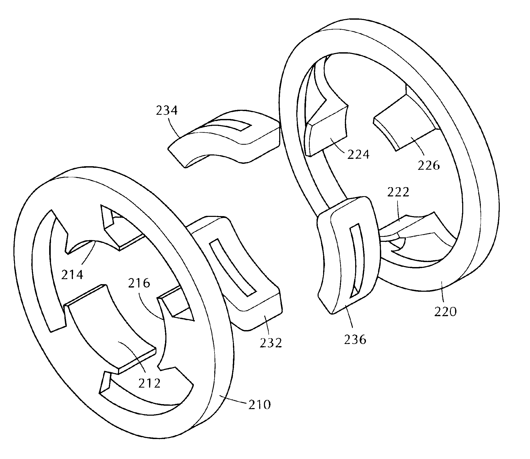
[0046]The electrical machine armature in this invention comprises a magnetic circuit component having one or more pieces and a polyphase winding with several coils. (FIGS. 2-12). The magnetic circuit component is preferably made from an iron-powder based composite magnetic material formed by pressing, molding or machining.

[0047]In this regard, it is not desirable to realize completely the magnetic circuit with a laminated material. Indeed, the circulation of an alternate magnetic flux in—three dimensions generates eddy currents in the sheets. However, it is possible to divide the magnetic circuit into several parts. The parts in which magnetic flux does not circulate in a plan (claws, corners) would be realized with a composite magnetic material, and the other parts in which the flux circulates in a plan (yoke, the bases of the claws) optionally could be made with a lami...


PUM


Abstract

A magnetic circuit component having a plurality of claws arranged in a plurality of rows, with the base of each claw connected to a common yoke. A plurality of non-interlaced coils constituting a multi-phase winding are included, with the coils being wound around the bases of corresponding claws, and being distributed uniformly in the direction of motion.

Description

BACKGROUND OF THE INVENTION[0001]The invention relates to electric machinery. In particular, this invention relates to the design of claw pole structures for polyphase electrical machinery.[0002]Electric machinery makes use of a changing magnetic field to produce either an electrical current or a mechanical force. In the case of electric machinery adapted to produce an electrical current, a magnetic field is passed over a wire coil, which induces the desired electrical current in the wire coil. In the case of electrical machinery used to produce a mechanical force, an electric current is passed through a wire coil, which causes the coil to be attracted to (or repelled by) an adjacent magnetic field, thereby yielding the desired force.[0003]The foregoing principles are commonly implemented in rotating electrical machinery. For example, in an electric generator or alternator, a rotating element, or rotor, is passed through the magnetic field produced at intervals by a stator, which ha...

Claims


Application Information

Patent Timeline
Patent Type & Authority Patents(United States)
IPC IPC(8): H02K1/14H02K21/16H02K21/22H02K1/24H02K3/18
CPCH02K1/146H02K21/16H02K21/22H02K2201/12
Inventor CROS, JEROMEVIAROUGE, PHILIPPE
Owner QUEBEC METAL POWDERS
Why Eureka
Try Eureka