Locating system and method for determining positions of objects
a positioning system and position information technology, applied in the field of positioning systems, can solve the problems of inability to obtain precise position information, unsuitable for long-range positioning tags, and limited range, so as to avoid undesirable increase in the number of receiving stations and limit communication range
- Summary
- Abstract
- Description
- Claims
- Application Information
AI Technical Summary
Benefits of technology
Problems solved by technology
Method used
Image
Examples
first embodiment
[First Embodiment]
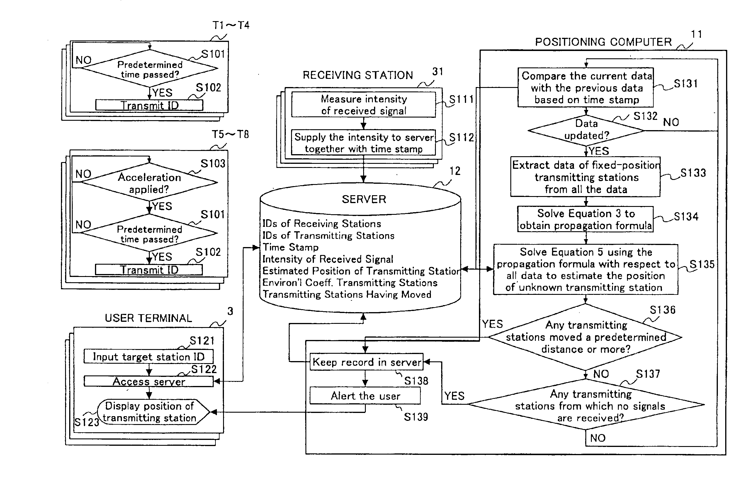
[0081]FIG. 5 schematically illustrates an example of the locating system 1 according to the first embodiment of the invention, and FIG. 6 illustrates the transmitting station 21 and the receiving station 31 used in the locating system 1. The locating system 1 includes transmitting stations 21 (T1-T8), receiving stations 31 (R1-R4), a server 12 connected to the receiving stations 31 and functioning as a data management unit, and a positioning computer 11 connected to the server 12. The locating system 1 also includes user terminals 3a-3c connected to the positioning computer 11. These components are connected to one another via LAN 2.
[0082]In the example shown in FIG. 5, the receiving stations 31 (R1-R4) are fixed, and their positions are known. The transmitting stations T1-T4 are attached to the receiving stations R1-R4, respectively, and therefore, the positions of the transmitting stations T1-T4 can be regarded the same as those of the receiving stations R1-R4. T...
second embodiment
[Second Embodiment]
[0118]FIG. 10 illustrates a schematic diagram of the locating system according to the second embodiment of the invention, and FIG. 11 illustrates the transmitting station 21 and the receiving station 31 used in the second embodiment. In the second embodiment, the receiving station periodically transmits an activation signal to the transmitting station. The transmitting station transmits an ID signal, which is different from the spontaneously generated ID signal, upon receiving the activation signal. Accordingly, the transmitting station generates three different kinds of ID signals, that is, (1) a periodic signal (i.e., the first ID signal) spontaneously generated by, for example, a built-in oscillator, (2) a signal (i.e., the second ID signal) generated in response to the activation signal, and (3) a signal (i.e., the third ID signal) generated when detecting a change due to external factors.
[0119]In the example shown in FIG. 10, both the activation signal and th...
third embodiment
[Third Embodiment]
[0159]FIG. 22 is a schematic diagram of the locating system according to the third embodiment of the invention, and FIG. 23 illustrates the transmitting station 21 and the receiving station 31 used in the third embodiment. In the third embodiment, the receiving station 31 has a means for measuring a transmission time required to acquire a type-a ID signal in response to the activation signal. Accordingly, as illustrated in FIG. 22, the receiving station R1 measures a transmission time t51 required to acquire the ID signal from transmitting station T5, in addition to the intensity e51. The other fixed-position receiving stations R2-R4 also measure the intensity and the ID signal transmission time.
[0160]In the third embodiment, a second correcting formula defining a relation between signal propagation time through the air and distance is used. By using the second correcting formula, the position of a transmitting station can be estimated more accurately. The ID signa...
PUM
 Abstract
Description
Claims
Application Information
 - R&D
- Intellectual Property
- Life Sciences
- Materials
- Tech Scout
- Unparalleled Data Quality
- Higher Quality Content
- 60% Fewer Hallucinations
Browse by: Latest US Patents, China's latest patents, Technical Efficacy Thesaurus, Application Domain, Technology Topic, Popular Technical Reports.
© 2025 PatSnap. All rights reserved.Legal|Privacy policy|Modern Slavery Act Transparency Statement|Sitemap|About US| Contact US: help@patsnap.com


