
Large angle azimuth recording and head configurations

a technology of large angle azimuth and recording head, which is applied in the field of magnetic storage recording techniques and devices, can solve the problems of exponential increase of error rate, narrow data track, and increase of possibility of erroneous data transfer, so as to substantially suppress or eliminate an adjacent track signal, and increase the overall tape data storage density

Inactive Publication Date: 2005-09-20
ADVANCED RES
View PDF44 Cites 58 Cited by
  • Summary
  • Abstract
  • Description
  • Claims
  • Application Information

AI Technical Summary

Benefits of technology

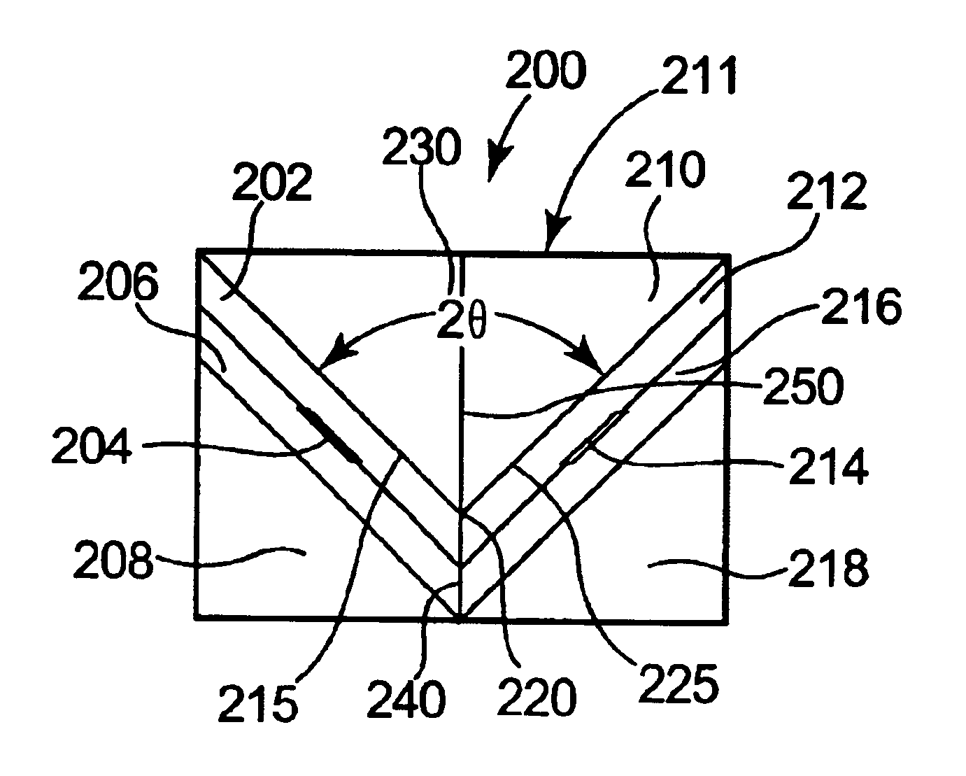
[0020]The present invention provides improved methods and systems for data recording and reading for increasing overall tape data storage density as such data is written at an azimuth angle with respect to a data track direction for linear or helical tape systems. The present invention advantageously utilizes azimuth recording so as to substantially suppress or eliminate an adjacent track signal by using data transitions arranged at a large azimuth angle, preferably up to the maximum suppression level that can be attained at 45 degrees. By increasing such suppression well beyond that which is minimally effective, which as taught by the prior art decreases tape density in the direction of the track, tape areal density can be significantly increased by writing data to decreased data track widths with overall more data tracks for a given tape width. With significant and preferably maximized suppression of signals from adjacent data tracks, resulting lower data reading signals from a more narrow selected data track (i.e. relatively smaller magnetic domains in area) can be effectively read regardless of read head size requirement. So, even if track density in the data track direction is reduced by increasing the azimuth recording angle, that effect can be overcome and largely surpassed by reducing track width and providing significantly more data tracks for a given tape width. The present invention also provides recording head structures that may be used for large angle azimuth recording.

Problems solved by technology

Thus, the read head size (as is also limited by read head performance characteristics) limits how narrow the data track can be, hence the maximum track density.
If a read head moves off the data track for whatever reason and begins to read a signal from the adjacent track, the possibility of erroneous data transfer increases.
More specifically, the error rate is known to increase exponentially as the read head moves further off the data track.
Reading narrow is unfortunately limited by making an acceptable read head that will still meet signal amplitude, SNR, and media defect sensitivity requirements.
There are a number of potential sources of read element to written track misregistration error, which error is systematic in that both the media and the drive are involved as potential sources of error.
The principal sources of error are: tape lateral motion, vibration in the head / actuator assembly, dimensional instability of the media substrate, and mechanical misalignments between read and write elements in manufacturing and assembly.
Probably the most significant limitation on tape track densities is the tendency for the tape to experience lateral tape motion, which is a tendency for the tape to shift laterally relative to the linear direction of tape motion.
During reading, lateral tape motion can cause misregistration of the read head over the track being read.
This build-up of potential misregistration of data tracks combined with other less significant potential sources of misregistration can result in a portion of the read element to be positioned over an adjacent data track, which, if significant enough, can cause an unacceptable level of data transfer errors.
However, as noted above, limitations of minimum signal amplitude, signal-to-noise-ratio, and sensitivity to media defects provides a lower limit as to how narrow the read element can actually be.
As such, the effective read head size limits how narrow a data track can be made.
One limitation of using a single head is that two degrees of freedom of movement, e.g. rotation and transverse shifting of the head, are required for track accessing and track following.
The mechanical joining of the read and write elements makes it difficult to achieve independent tracking of the read and write elements without such multiple freedoms of movement.
This provision of additional leads adds stiffness to the system that can inhibit or interfere with its motion capabilities.
It is necessary during a read-while-write function (data writing followed by confirmation read) that the writing and reading are accomplished in separate gaplines because of the high level of interference that may be created as a result of the relatively much larger write signal coupling into the read signal, which interference can still occur if the write element (or array) and read element (or array) are in too close of a proximity to one another.
The closer the proximity of the two gaplines, the larger is the potential for interference.
However, this system is limited in the ability to precisely position the read and write elements since the two head modules form a monolithic head and the read and write gaplines cannot be independently positioned.

Method used


Image

  • Large angle azimuth recording and head configurations
  • Large angle azimuth recording and head configurations
  • Large angle azimuth recording and head configurations

Examples


Embodiment Construction

[0044]The present invention is premised upon the discovery that by increasing azimuth angle, data storage density for a given tape width can be increased significantly more than the cosine θ loss in linear track density, as discussed above in the Background Section, allowing a greater increase in areal density than is possible with orthogonal or conventional azimuth recording. In particular, using an azimuth angle that is higher than current azimuth recording techniques, preferably over 30 degrees, and most preferably at or near 45 degrees, can substantially reduce or eliminate all undesirable side track signals and allowing the read transducer to be extended to two times or more of the data track width. The size of the read transducer would be effectively limited, however, by any further track of a similar transitional azimuth (i.e. by the track after the adjacent one). A large angle azimuth data track in accordance with the present invention can be advantageously decreased in widt...


PUM


Abstract

Large angle azimuth recording methods and devices. In one aspect of the invention methods of recording one or data tracks having data transitions oriented at a large azimuth angle are provided. In another aspect of the invention methods of reading a data track having data transitions oriented at a large azimuth angle are provided. Such methods include steps of suppressing a side track signal. In other aspects of the invention, head modules and devices for writing and / or reading large azimuth angle data tracks are provided.

Description

PRIORITY CLAIM[0001]This patent application claims priority under 35 U.S.C. §119(e) from U.S. Provisional Patent Application No. 60 / 469,521, filed on May 9, 2003, by Dugas et al., U.S. Provisional Patent Application No. 60 / 469,518, filed on May 9, 2003, by Dugas et al., and U.S. Provisional Patent Application No. 60 / 452,206, filed on Mar. 5, 2003, by Dugas et al., each of which application is commonly owned by the assignee of the present application and the entire contents of which are incorporated herein by reference.FIELD OF THE INVENTION[0002]The present invention relates generally to magnetic storage recording techniques and devices. In particular, the present invention relates to large angle azimuthal recording for linear serpentine tape systems and head configurations for use in such recording for achieving high recording densities.BACKGROUND OF THE INVENTION[0003]Various magnetic recording techniques exist for recording data to and from magnetic storage media, such as magneti...

Claims


Application Information

Patent Timeline
IPC IPC(8): G11B5/265G11B5/008G11B5/54G11B20/12G11B5/31G11B5/48G11B5/23G11B5/55
CPCG11B5/00813G11B5/2651G11B5/3103G11B5/4893G11B5/54G11B20/1205G11B5/23G11B5/2652G11B5/313G11B5/5504G11B5/5513
Inventor SCHWARZ, THEODORE A.DUGAS, MATTHEW P.
Owner ADVANCED RES
Learn More