
Parameter estimator for a multiuser detection receiver

a multi-user detection and estimator technology, applied in diversity/multi-antenna systems, error detection/prevention using signal quality detectors, amplitude demodulation, etc., can solve the problem of virtually impossible conditions, no method for estimating parameters, and dent design not working, etc. problem, to achieve the effect of accurate estimation of signature waveforms

Active Publication Date: 2005-09-20
COLLISION COMM INC
View PDF10 Cites 30 Cited by
  • Summary
  • Abstract
  • Description
  • Claims
  • Application Information

AI Technical Summary

Benefits of technology

"This patent describes a method for accurately estimating the signature waveforms of multiple co-channel interfering digital signals in a multi-user detection receiver. The method uses a parameter estimator that accurately locates the training sequences in each frame of the received baseband signal and calculates the average noise power and the number of active users in each frame. This method reduces the error rate in a multi-user detection receiver and improves the accuracy of identifying the users transmitting signals. The patent also describes a multi-user communication system that includes a receiver with a parameter estimator for accurately estimating the signature waveforms of each user in the received baseband signal."

Problems solved by technology

These patent applications estimate the parameters by assuming that signals are added to the propagation channel one at a time, but give no method for estimating parameters when the channel is always occupied by multiple users.
Unfortunately, Dent's design will not work when the bit transitions of the various co-channel transmitters are not aligned in time at every antenna (a virtually impossible condition to meet).
These effects are normally mitigated through the use of adaptive equalizers, but these equalizers do not work in the co-channel interfering signal case.
The second drawback of this approach is that it requires multiple (and usually a large number) of antennas.
In the case of short “snapshots” (vectors of received waveform samples), the correlation process will produce noisy data, and inaccurate known symbol sequence position estimates.
In addition, the waveforms correlated against do not include the (unknown) channel impulse response, and will therefore also be adversely affected by leaving those out of the correlation equation.

Method used


Image

  • Parameter estimator for a multiuser detection receiver
  • Parameter estimator for a multiuser detection receiver
  • Parameter estimator for a multiuser detection receiver

Examples


Embodiment Construction

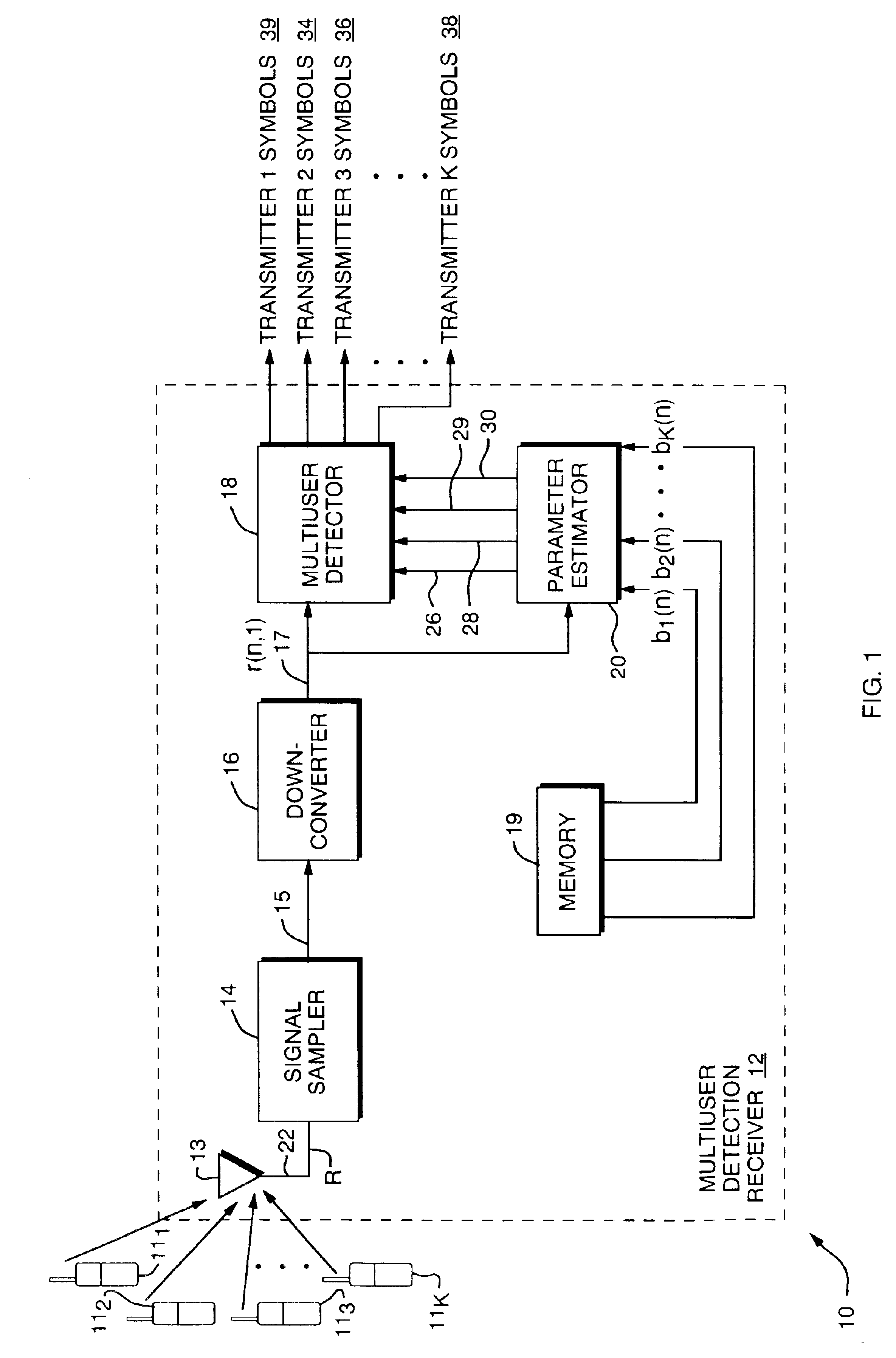
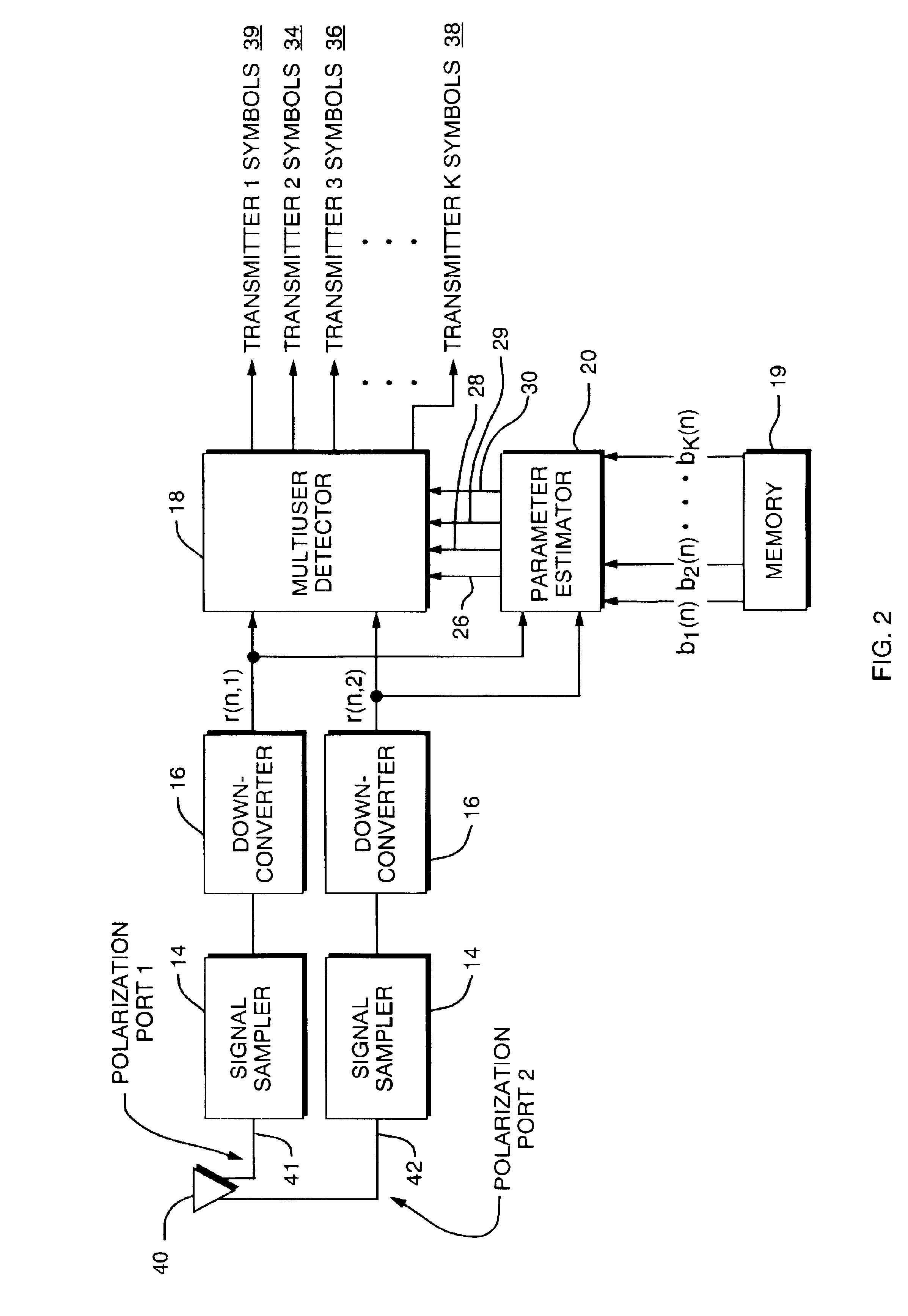
[0029]Referring to FIG. 1, a system block diagram is shown of a Communication System 10 comprising a Multiuser Detection (MUD) Receiver 12 and a plurality of User Transmitters 111 to 11K which are all simultaneously transmitting co-channel, interfering digital signals, all on the same frequency, all using the same type of modulation scheme such as digital phase shift key (PSK) or quadrature amplitude modulated (QAM) signals, with the same nominal data rate. Each of the User Transmitters 111 to 11K has a unique, known training sequence. The training sequences are roughly aligned as received at a Receiver Antenna 13, so that the training sequences mostly overlap. This type of synchronization is normally provided in communication systems through the use of a synchronization signal transmitted from a unit co-located with the MUD receiver 12. Alignment of the symbol transitions is not required. A Table at the end of the Description summarizes the nomenclature used herein.

[0030]The MUD Re...


PUM


Abstract

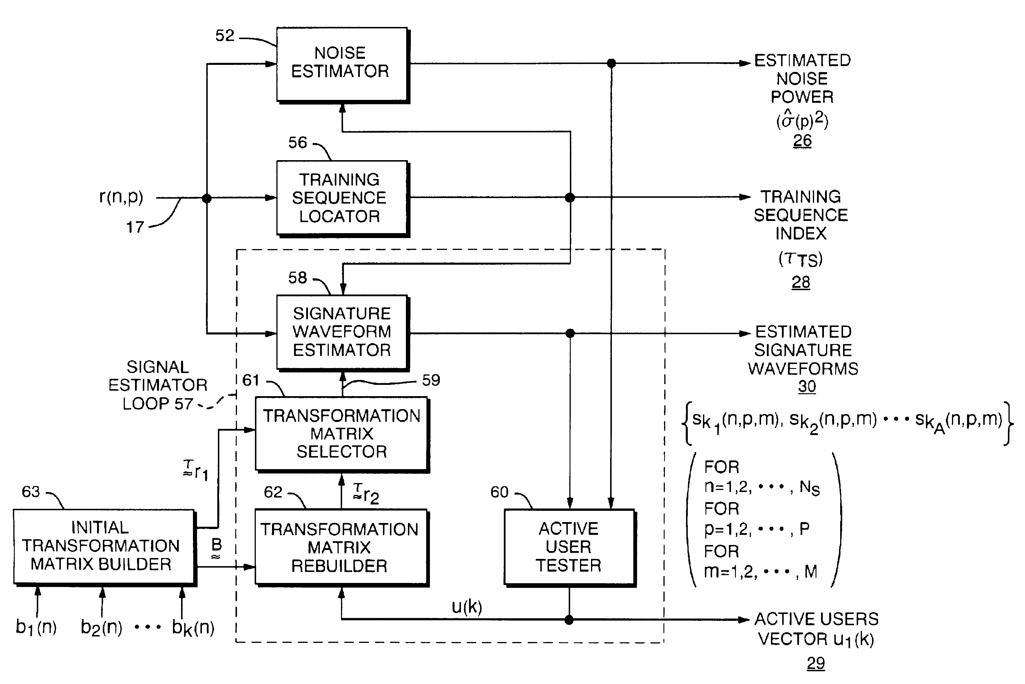
A Parameter Estimator for accurately estimating signature responses of multiple co-channel interfering digital transmission signals. The Parameter Estimator is used in a Multiuser Detection (MUD) Receiver to significantly reduce the error rate. The Parameter Estimator comprises a plurality of software components, including a Signature Waveform Estimator, Training Sequence Locator, Noise Estimator, Active Users Tester, Initial Transformation Matrix Builder, a Transformation Matrix Rebuilder, and a Transformation Matrix Selector, and generates an estimated noise power, a training sequence index and estimated signature waveforms.

Description

CROSS REFERENCE OF RELATED APPLICATIONS[0001]This is a nonprovisional patent application claiming priority of provisional application for patent Ser. No. 60 / 372,956, filed Apr. 16, 2002.STATEMENT OF GOVERNMENT INTEREST[0002]This invention was made with the support of the United States Government. The United States Government may have rights in this invention.BACKGROUND OF THE INVENTION[0003]1. Field of the Invention[0004]This invention relates to a multiuser communication system and in particular to a multiuser detection (MUD) receiver for jointly demodulating co-channel interfering digital signals using estimates of the parameters of each individual signal, as distorted by their unique propagation channels, such estimates being generated by a parameter estimator.[0005]2. Description of Related Art[0006]Prior art methods for multiuser detection are included in the textbook “Multiuser Detection, Cambridge University Press, 1998 by Verdu. Verdu describes several different types of mu...

Claims


Application Information

Patent Timeline
Patent Type & Authority Patents(United States)
IPC IPC(8): H04L1/06H04L1/24H04B1/707H04L1/02H04L1/20H04B7/08
CPCH04B1/71057H04B7/0851H04L1/06H04L1/20H04L1/24
Inventor TAYLOR, MATTHEW A.NIEDZWIECKI, JOSHUA D.MACLEOD, ROBERT B.
Owner COLLISION COMM INC
Learn More