Volume imaging system

Inactive Publication Date: 2005-09-20
GENERAL ELECTRIC CO
View PDF9 Cites 85 Cited by
  • Summary
  • Abstract
  • Description
  • Claims
  • Application Information

AI Technical Summary

Benefits of technology

[0007]In one specific embodiment, the system includes an operator console having an exam prescription subsystem which specifics the manner in which the imaging system acquires data, a visualization subsystem responsible for the presentation layout and display of the acquired images and processed data, an archive subsystem for permanent storage and future retrieval of imaging data, a filming subsystem which transfers data onto film, and a networking subsystem that transfers data via a network to or from other imaging systems. The exam prescription subsystem is responsible for determining how the patient exam data is acquired. Numerous parameters are required to specify an acquisition including a sequence of slice locations, slice thickness, field-of-view, scanning technique, and reconstruction algorithm. In addition, volume imaging and filming presentation parameters may also be included in the exam scan prescription. Until now, the scan prescriptions did not include volume imaging and filming parameters. These parameters can be entered explicitly by the technologist or, more commonly, the parameters are defined by selecting a particular scan protocol as is well known in the art. The exam prescription subsystem generates a scan prescription and the prescription is transmitted to the data acquisition system (DAS). The scan protocol can also include contrast injection parameters by including contrast injection tracking as part of the protocol. This could be extended to include control of a contrast injector to execute the stored contrast instructions.
[0008]The DAS collects the acquisition data in accordance with the prescription, and provides the acquired data to an image reconstructor for generating a series of images from the acquired data which can be used to produce a volumetric model. A volumetric model typically includes a three dimensional (or higher) rectilinear array of values, often with a single scalar value per sample.
[0009]The visualization subsystem controls presentation of all relevant imaging data to the operator. The data includes, for example, 2D images, 3D projections, patient data, annotation, and measurements. Subsystem 52 implements several visualization features such as routine display, cross reference, autoview display, volume autoview display, and other forms of display, using one or more windows or viewports, where each window may include its own set of visualization parameters. As described below in more detail, visualization subsystem includes several components to filter, classify, render, annotate, and take measurements.

Problems solved by technology

With such known systems, 3D images and measurements typically are not generated during a scan due to the processing requirements associated with generating such 3D images and measurements.

Method used


Image

  • Volume imaging system
  • Volume imaging system
  • Volume imaging system

Examples


Embodiment Construction

[0027]The present invention is directed, in one aspect, to a volume imaging system. The invention can be practiced in many different medical imaging modalities including computed tomography (CT), magnetic resonance (MR), and ultrasound. Therefore, although the invention is sometimes described herein in the context of a CT imaging system, it should be understood that the invention is not limited to practice in CT and can be used in other modalities as well.

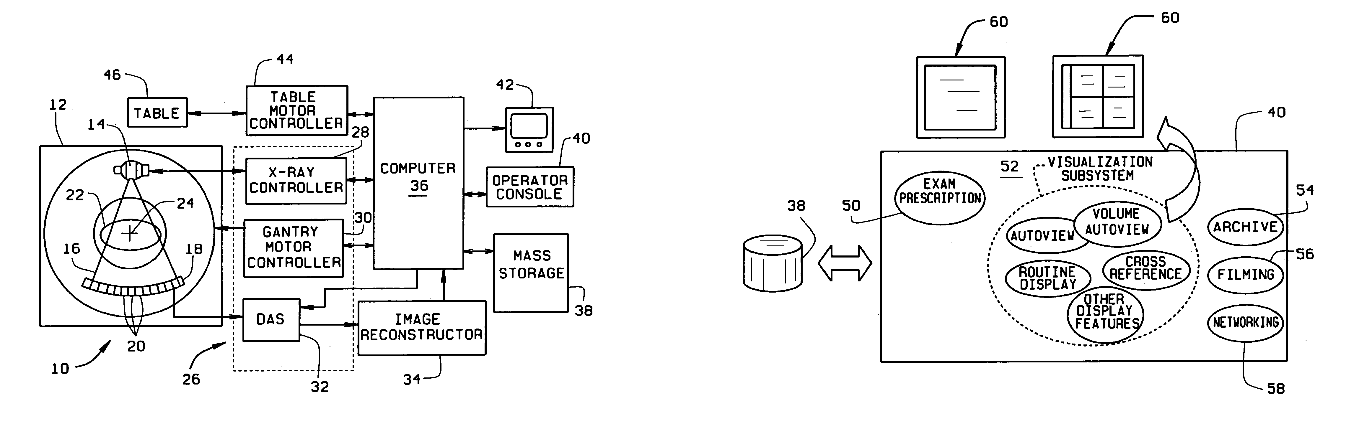
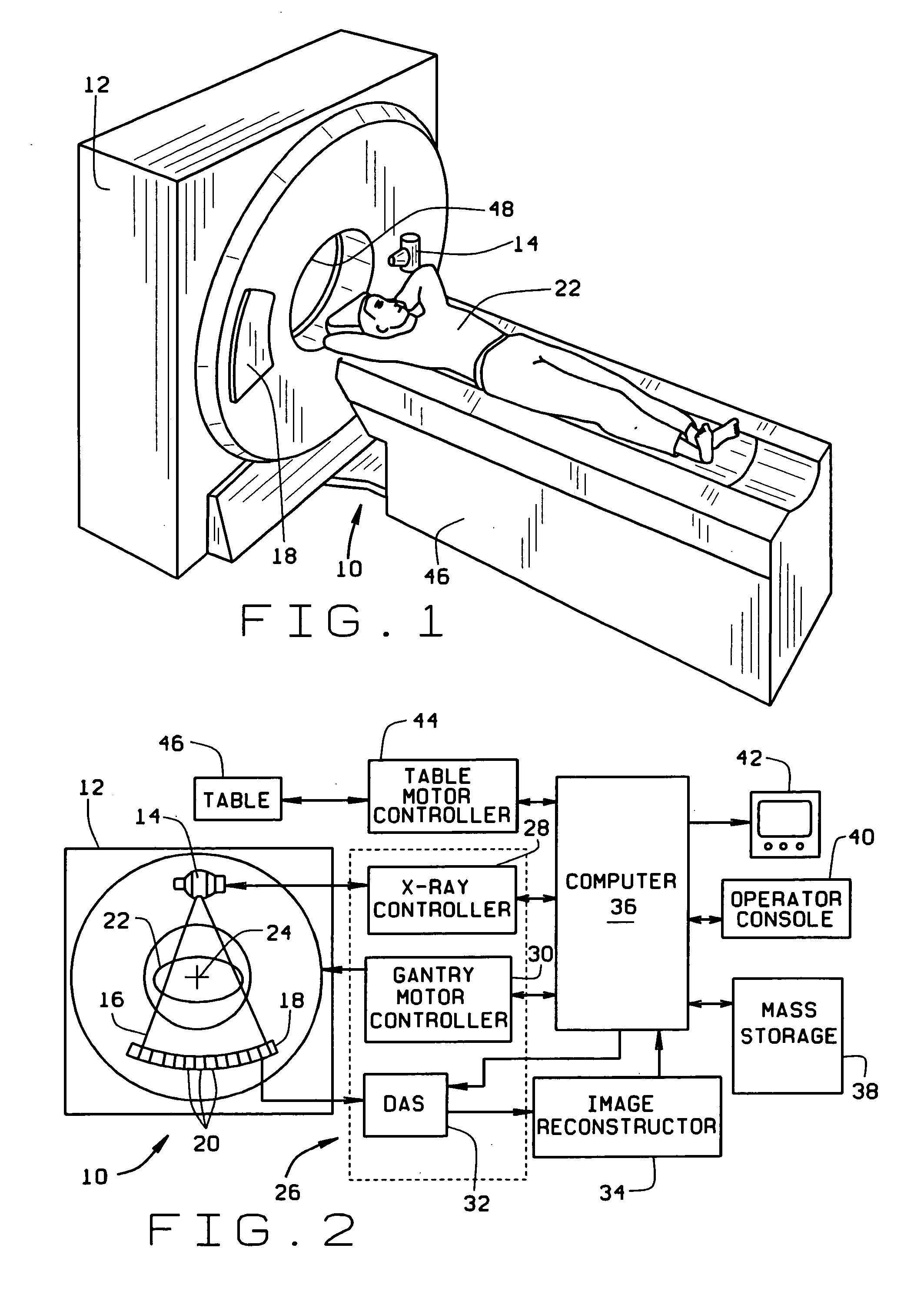
[0028]With respect to CT, and referring to FIGS. 1 and 2, a computed tomograph (CT) imaging system 10 is shown as including a gantry 12 representative of a “third generation” CT scanner. Gantry 12 has an x-ray source 14 that projects a beam of x-rays 16 toward a detector array 18 on the opposite side of gantry 12. Detector array 18 is formed by detector elements 20 which together sense the projected x-rays that pass through a medical patient 22. Each detector element 20 produces an electrical signal that represents the intensity of...


PUM


Abstract

A volume imaging system which progressively constructs, analyzes, and updates three dimensional models while acquiring cross-sectional data is described. The system constructs and displays three-dimensional renderings, and performs quantitative calculations in real time during the imaging system data collection process, displays interactive three-dimensional renderings in a traditional post-data collection process, as well as prescribes, archives, films, and transmits rendering procedures, parameters, renderings, measurements, and processed data, during data collection and post-acquisition.

Description

CROSS REFERENCE TO RELATED APPLICATION[0001]This application claims the benefit of U.S. Provisional Application No. 60 / 109,987, filed Nov. 25, 1998 and is a continuation-in-part (CIP) of application Ser. No. 09 / 139,438, filed Aug. 25, 1998 and issuing as U.S. Pat. No. 6,141,398 assigned to the present assignee.BACKGROUND OF THE INVENTION[0002]This invention relates generally to medical imaging and more particularly, to methods and systems for generating three dimensional volumetric data sets.[0003]Known medical imaging systems, such as computed tomography, magnetic resonance, and ultrasound imaging systems, generate 2-dimensional (2D) images for real time visualization of cross-sectional data. More particularly, and with such known systems, 2D images are immediately displayed following acquisition and reconstruction of the cross-sectional data. The real time display of 2D images facilitates ensuring that the scan is proceeding with appropriate parameters, e.g., slice thickness, to m...

Claims


Application Information

Patent Timeline
Patent Type & Authority Patents(United States)
IPC IPC(8): G06K9/00
CPCG06T19/00Y10S128/922Y10S128/916G06T2210/41
Inventor AVILA, RICARDO SCOTTMILLER, JAMES VRADENBURGSENZIG, ROBERT FRANKLINHE, HUI DAVIDOKERLUND, DARIN ROBERT
Owner GENERAL ELECTRIC CO
Why Eureka
Try Eureka