Measurement of fiber strain during processing

a technology of fiber strain and processing, applied in the direction of force measurement by measuring optical property variation, instruments, optical elements, etc., can solve the problems of affecting the ultimate mechanical strength of the fiber, insufficient to induce sub-critical growth of preexisting flaws within the fiber, and reducing the reliability of the field fiber

Inactive Publication Date: 2005-09-20
CORNING INC
View PDF11 Cites 27 Cited by
  • Summary
  • Abstract
  • Description
  • Claims
  • Application Information

AI Technical Summary

Benefits of technology

[0012]The measurement may be repetitively performed at a high sampling rate of, for example, greater than 7 kHz to provide a dynamic measurement of the strains experienced by each sensor. A fiber bearing a plurality of such sensors may be continuously passed through a realistic manufacturing or other stressing process while such dynamic strain measurement is being performed to measure strain at one or more points in the process performed under realistic conditions.

Problems solved by technology

Even if the total time that the fiber is being stressed at any point is relatively short, that time may be sufficient to induce sub-critical growth of preexisting flaws within the fiber.
Such flaws are likely to impact the ultimate mechanical strength of the fiber, thereby decreasing the reliability of the field fiber.
Heretofore, direct measurements of the stresses exerted on an optical fiber during high-speed processing has not been possible.

Method used


Image

  • Measurement of fiber strain during processing
  • Measurement of fiber strain during processing
  • Measurement of fiber strain during processing

Examples


Embodiment Construction

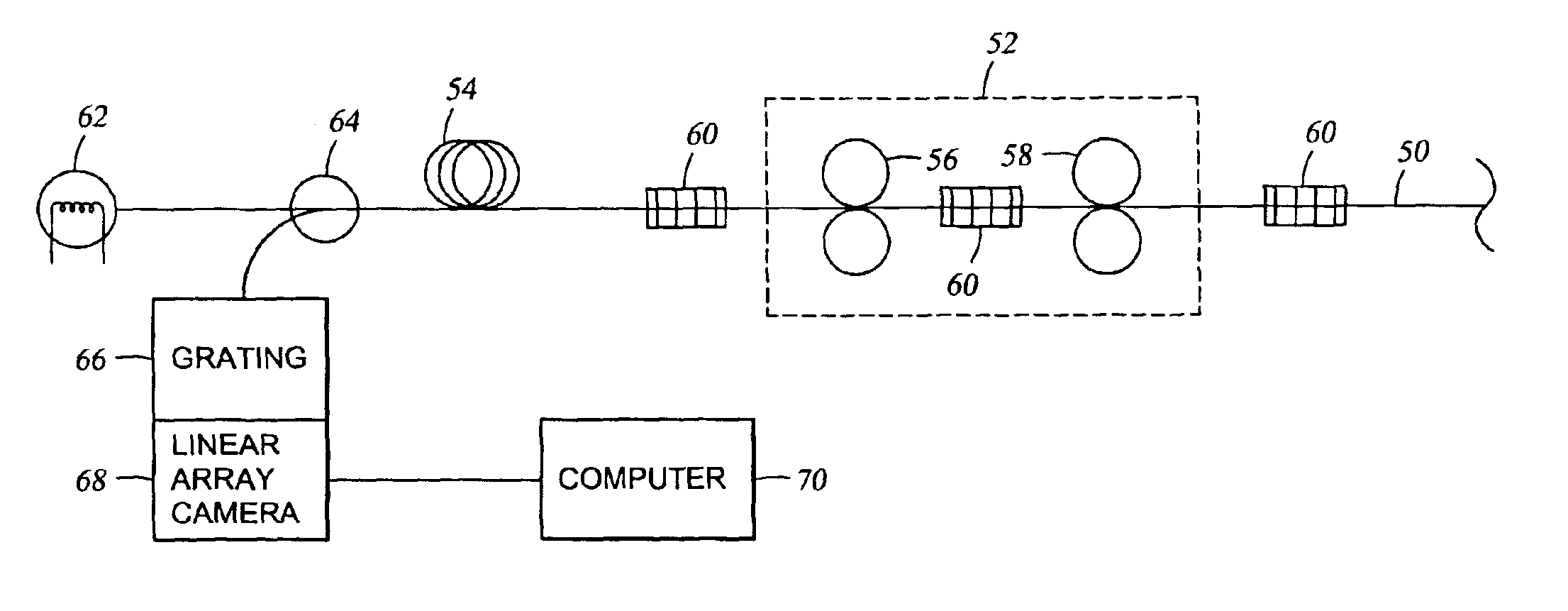
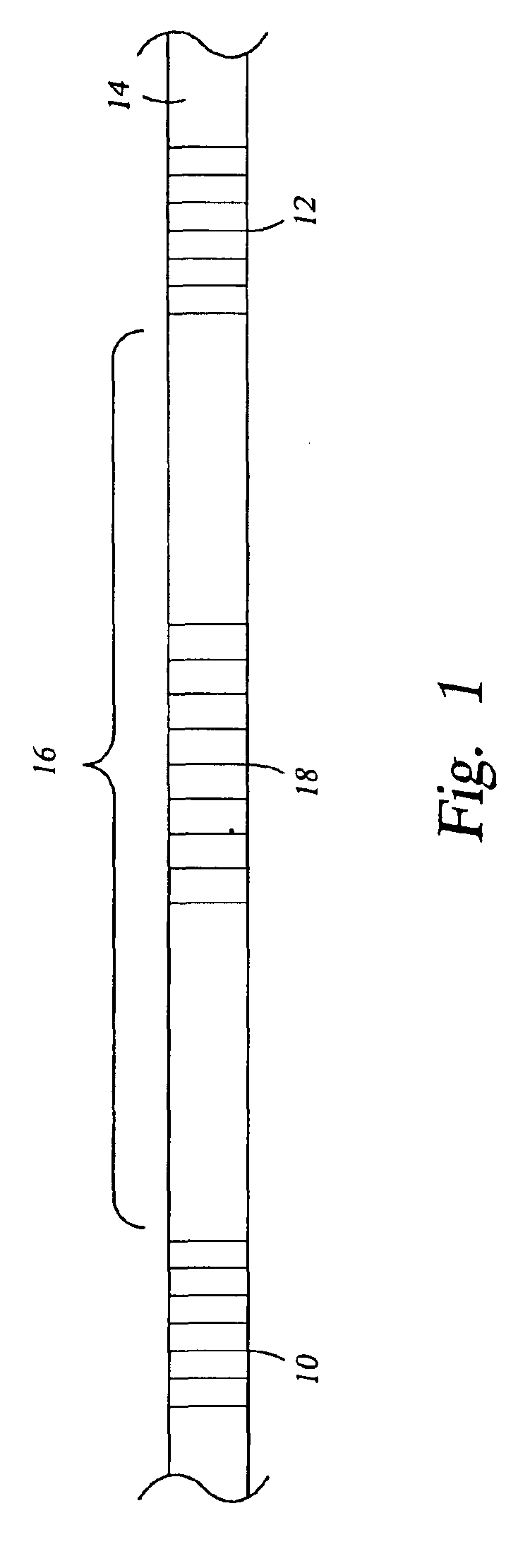
[0021]Strain and temperature can be dynamically measured in a fiber being processed by an optical method in which two types of sensors are written into a fiber. A sensor as used here refers to a structure impressed into the fiber to form an axially extending optical structure that produces a wavelength dependent spectrum for optical reflection of light axially propagating along the fiber although the transmission mode may be used if desired. A pair of associated sensors of different types is called a hybrid sensor.

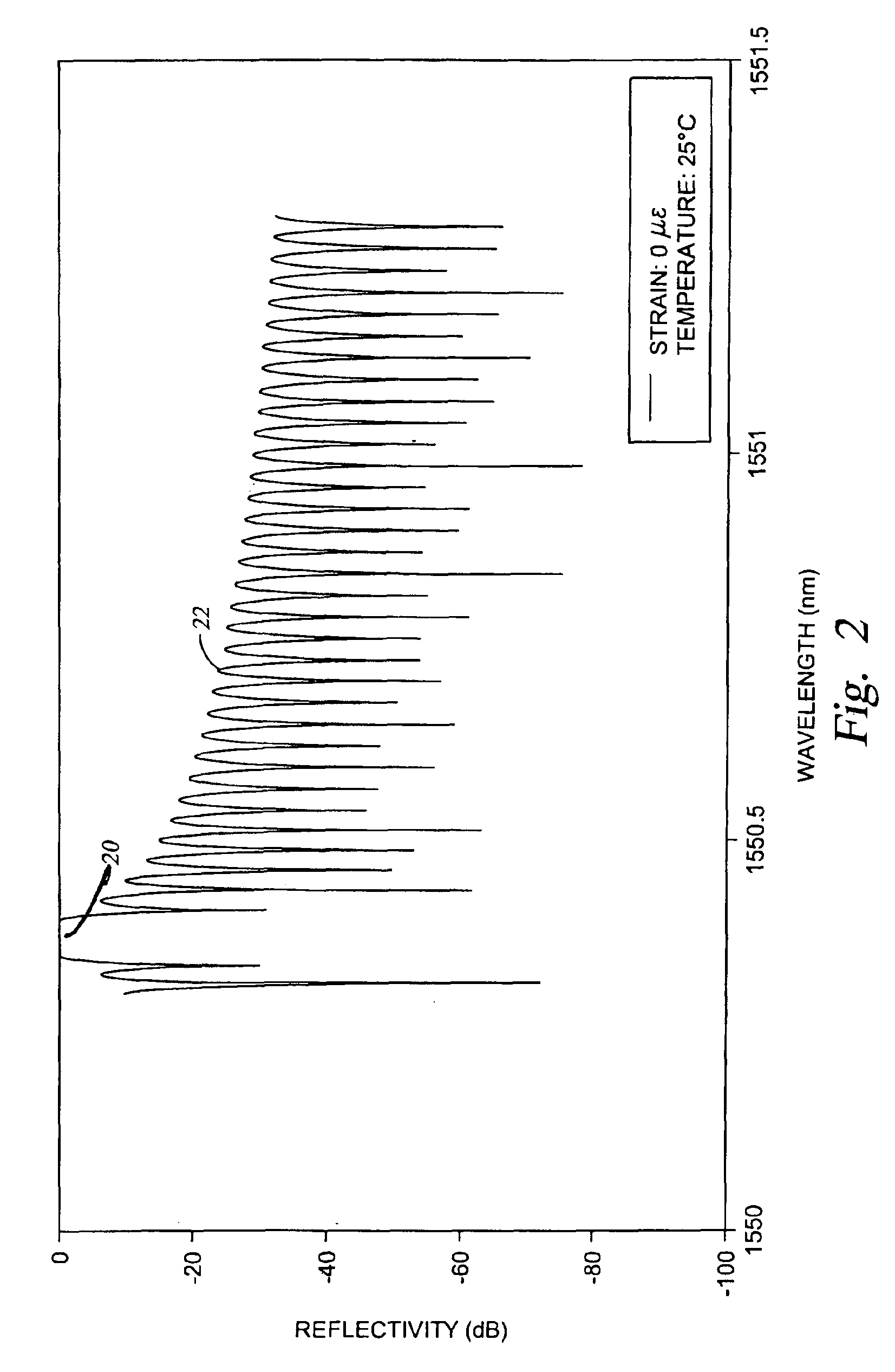
[0022]One such sensor is a fiber Bragg grating (FBG) consisting of a pattern of refractive index variations called lines formed transversely to the fiber axis on a fixed pitch. A large number of lines is sufficient to form a Bragg grating. When operated in first order, a Bragg grating will reflect light having a wavelength that is twice the pitch of the Bragg grating, taking into account the effective refractive index of the fiber.

[0023]Another such sensor is a Fabry-Perot...


PUM

PropertyMeasurementUnit
temperaturesaaaaaaaaaa
lengthsaaaaaaaaaa
lengthsaaaaaaaaaa

Abstract

A method and system for determining strain impressed on an optical fiber at a possibly indeterminate temperature. The fiber (14) is formed with at least two sensors having different strain and temperature characteristics, preferably a Bragg Fabry-Perot sensor having a Fabry-Perot cavity (16) formed between two like Bragg gratings (10, 12) and another Bragg grating 18 of a different pitch written into the Fabry-Perot cavity. Many such pairs can be written if the Bragg gratings reflect in different bands. The fiber is irradiated with broadband light, and the reflection is spectrally separated to produce separate spectra for all sensors. Wavelength shifts from two types of sensors can be correlated with strain and temperature according to predetermined variations of the shifts with known strain and temperature changes.

Description

[0001]This application claims priority to and the benefit of U.S. Provisional Application No. 60 / 311,166 filed Aug. 9, 2001 and U.S. Provisional Application No. 60 / 362,115, filed Mar. 5, 2002.BACKGROUND OF THE INVENTION[0002]1. Field of the Invention[0003]The invention relates generally to optical measurement systems. In particular, the invention relates to a method of measuring strain induced in an optical fiber during its manufacture or other processing.[0004]2. Background Art[0005]Optical fiber is being manufactured in large quantity for use as the transmission medium in communications networks. Numerous performance and reliability requirements imposed on the manufactured fiber can be met only by continued monitoring of the manufacturing process and its effect on the fiber. The manufacture and further processing of optical fiber involves several processes subjecting the fiber to a degree of mechanical stress and to moderately high temperatures, for example up to 125° C. The stres...

Claims


Application Information

Patent Timeline
Patent Type & Authority Patents(United States)
IPC IPC(8): G01D5/353G01L1/24G01D5/26
CPCG01L1/246G01D5/35316G01D5/35312
Inventor SMITH, JAMES A.
Owner CORNING INC
Why Eureka
Try Eureka